After playing around with various kinds of hole cutters, mills, angle vises, and so on, I’ve settled on the best method for cutting fishmouths in tube ends so they fit together properly when building a tube frame with round tubing. Since the tubes will be welded they don’t have to be perfect as you would get by using a milling machine. Also, the typical joint has several tubes meeting which need to accomodate each other, and on a milling machine this would take a separate setup for each tube at each joint, taking an inordinate amount of time. Forcing Solidworks to show the correct shape of the ends of each tube requires some real work, an explanation of which I found over on the LoCost website. I’m going to provide a modified and updated tutorial here.
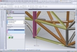
The first thing to understand is that each tube must be fully welded before adding the next tube. This makes the finished structure much stronger than if you tacked all the tubes in place and simply welded around the remaining visible joints. Here’s an example:
Solidworks Tutorial
Although the following tutorial may look long and complicated, once you understand what’s going on each step will only take seconds. And believe me, it’s much faster than grinding a tube to fit using trial and error. More accurate, too.

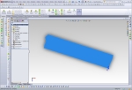
First, create a weldment profile with the correct outside diameter, a thickness of 0.1mm, and a gap of 0.1mm as shown.

Each tube will need to be trimmed to the tubes around it, reflecting the order in which they will be assembled. Insert > Weldment > Trim/Extend. Check your trims.

Align the views horizontally by right clicking on one view and choosing Drawing Views > Align Horizontally by Origin.

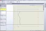
Crop each view by first drawing a rectangle with 4 lines. The automatic draw rectangle won't work because it uses the unrotated axes.

Crop the view by selecting the four lines of the rectangle, right click and choose Drawing Views > Crop View


Good day Sir,
Well done on the tutorial. I have had to figure out that tubing notch method on SolidWorks as well. It’s nice to know that others use this method!
Thank you for posting about this project as it has helped me to know of things that I am on track with and things to consider.
Cheers,
Jasin
There is an easier way… software by BendTech. Not only can you easily design your tubular chassis (and sheet metal) and rotate it in 3D, but included are tools to specify the order of tubes in each joint and to print templates which wrap around each tube to cut… very cool. They also have tools included to tell you exactly how to make any bends for bent parts. I could go on and on, but it has everything you need for design and it’s very easy to use. I’ve been a user for 10+ years… and the underlying CAD system is Solidworks.
Check it out at http://www.BendTech.com... inexpensive (but very valuable) software for anyone that wants to build a tube chassis. They have done an amazing job.