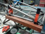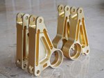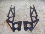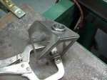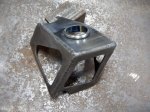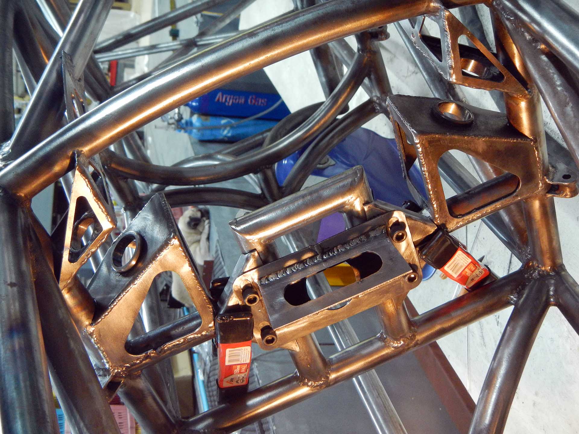
Steering rack mount, ready to weld gussets.
Next step in getting the car rolling is to mount the steering rack. These parts were not laser cut but were cut with angle grinders and my bandsaw, because they’re, um, a design improvement. Yeah, a design improvement, that’ll work. It took me months to find a blade for my bandsaw, because Thailand. Anyway, now it’s useful for these kinds of tasks.
Once again we have something that looks simple, but took a great deal of thinking to arrive at. As Steve Jobs said, “Simple can be harder than complex: You have to work hard to get your thinking clean to make it simple.” I used to do almost exactly what Steve Jobs did; in fact, he once called my boss to persuade him to cancel the design we were working on, because Jobs was going to do it better (he didn’t). So I understand precisely what Jobs meant about simplicity. That might help explain why this was my fifth complete design for this subassembly. One downside of mechanical design: when you’ve sweated out an elegant design, anybody can take a casual glance at it and say “OBviously”. To which I reply, “OK, there’s probably an even better design out there somewhere. Let’s see you find it.”
Also attached are a few of the finite element analysis (FEA) tests that I performed to verify and improve this design.
-

- FEA result: upper tube compression
-

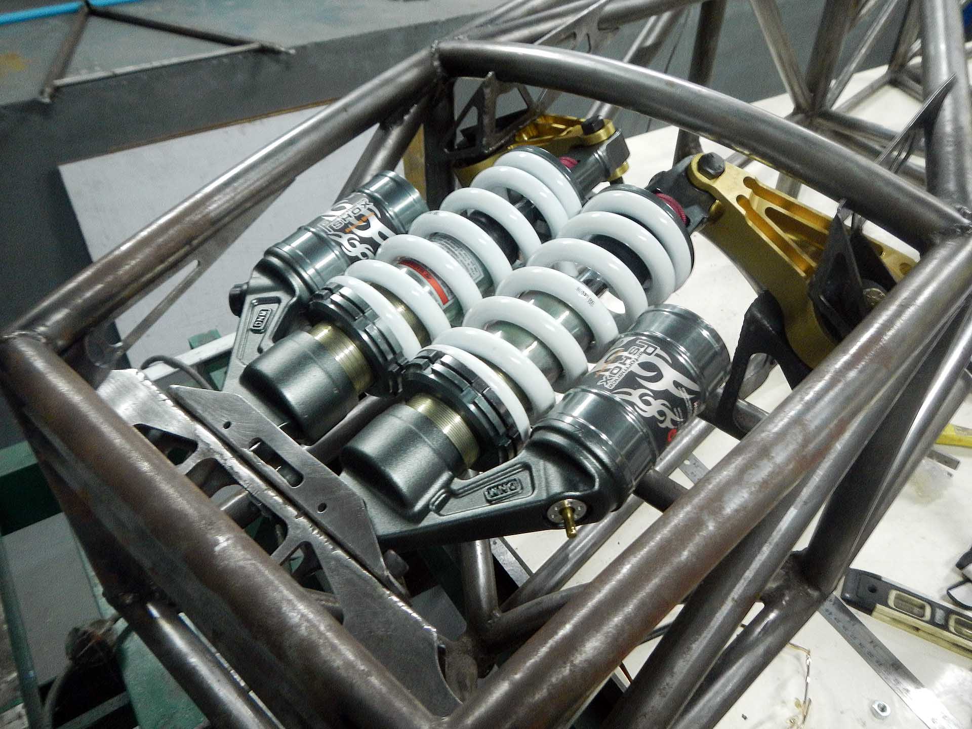
- FEA result: suspension rocker arm force
-

- FEA result: steering rack in 100G bump
-

- FEA result: 1000 pound steering force
-

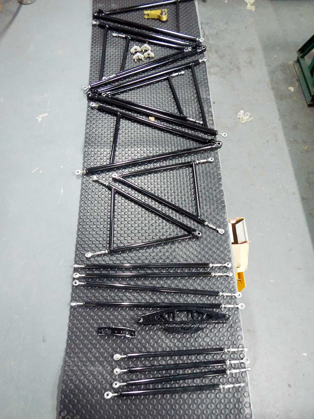
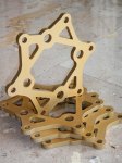
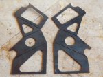
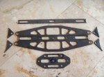
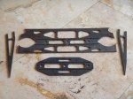
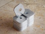
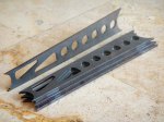
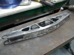
- Complete set of parts hand cut
-

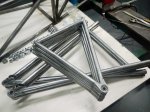
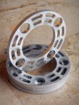
- Subassemblies welded
-

- Welding finished
-

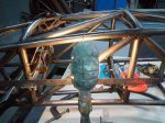
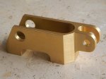
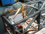
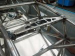
- Bracket installed