Fabricating the Shifter Assembly & Linkage

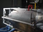
Assembled

Assembled shifter mechanism

I looked through a bunch of street car transmission shifter cables, brought a couple of them back to the lab, and decided on one that was the correct length, light, and low friction. Everything else was fabricated…

The car will use a Suzuki GSX-R1000 engine, which has a 6-speed sequential transmission, meaning the shifter only has two movements: shift up, and shift down.

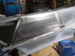
Attaching the Body

Starting to look like a car

Almost finished mounting the body

Not much to say about this one… Just lots more piddly little brackets. The large bracket at the tail is necessary as that will be where the rear impact absorber will mount. Had to make some changes just behind the driver’s left shoulder to allow access to the fuel filler.

Building the Floor Pan, Floorpan, Belly Pan, Whatever

Floor Pan

Formula 1000 race car floorpan with front keel

In my continuing effort to get everything welded onto the frame so can paint it, it’s time to build the floor pan. SCCA rules allow the floor pan to be a stressed skin, so this one fully welded around outside and to all crossmembers. To anyone who wants to learn to weld better, I recommend welding a floorpan. That’s a lot of welding. None of these pieces were laser cut– templates were made in plastic sheeting, transferred to sheet steel, and cut out with an angle grinder. Wear hearing protection. And eye protection. And lung protection. And heavy gloves up to your elbow. Angle grinders can mess you up.

The floor pan around  front keel is of special interest. Some parts have a single curve which is easily fabricated, but two of the pieces have a compound curve which can’t just be bent. They have to be pounded into submission to make them fit. As this is my first attempt  at metal shaping, I started out tentatively. After a lot of pounding I was getting nowhere and got angry. It turns out this is what you need to do. Pound the crap out of it, then fix the area around the big dent you just made, and eventually it takes shape. An English wheel would have been useful, but building or buying one is a big project.

There are two layers of steel under the fuel tank and the driver’s butt, one under the legs. Should be stiff, strong, and safe. And now, on to the photographs. I suffered through this. Now it’s your turn:

Removable Engine-Compartment Frame Rail

My original plan was to make the engine install from the bottom as I’d owned Porsche 911s for most of my life, but feedback on the ApexSpeed.com forum made me change my mind. The change was fairly simple, requiring only making the upper right engine-compartment frame rail removable. Taking an angle grinder to cut a big chunk out of my finished frame definitely made me measure seven times, cut once.

Fabricating GSX-R1000 Engine Mounts

Sorry for the long delay since the last blog entry. A lot of water has gone under the bridge since then. But don’t worry, the project has continued, although with some big distractions. I’ll be trying to catch up on my blogging in the next few weeks.

Next up is fabricating the engine mounts for the 2007-8 Suzuki GSX-R1000 motorcycle engine. I surveyed the state of amateur formula-car engine mounts, and decided a lot of them are inadequate. This video got me to thinking: https://www.youtube.com/watch?v=m1j7hmJmSJA as my car should be faster than a Ferrari 458. Some might be skeptical of that speed comparison; if you are, take a look at this comparison of a Porsche 911 Turbo versus a formula 4 car: https://www.youtube.com/watch?v=e8WyvVbVu4k . A formula 1000 car should compare favorably with a formula 4 car. Either way, you lose a lot of torsional rigidity with the large open hole to mount the engine, and I hope to recover much of that with a strong triangulated set of engine mounts.


Designing and Fabricating the Steering Rack Mount

Rack Mount

Steering rack mount, ready to weld gussets.

Next step in getting the car rolling is to mount the steering rack. These parts were not laser cut but were cut with angle grinders and my bandsaw, because they’re, um, a design improvement. Yeah, a design improvement, that’ll work. It took me months to find a blade for my bandsaw, because Thailand. Anyway, now it’s useful for these kinds of tasks.

Once again we have something that looks simple, but took a great deal of thinking to arrive at. As Steve Jobs said, “Simple can be harder than complex: You have to work hard to get your thinking clean to make it simple.” I used to do almost exactly what Steve Jobs did; in fact, he once called my boss to persuade him to cancel the design we were working on, because Jobs was going to do it better (he didn’t). So I understand precisely what Jobs meant about simplicity. That might help explain why this was my fifth complete design for this subassembly. One downside of mechanical design: when you’ve sweated out an elegant design, anybody can take a casual glance at it and say “OBviously”. To which I reply, “OK, there’s probably an even better design out there somewhere. Let’s see you find it.”

Also attached are a few of the finite element analysis (FEA) tests that I performed to verify and improve this design.

Building the Body Buck: Part 1, Ribs & Foam

Here’s what we’re building, sort of. Rather than build a CAD model of an actual assembly of stringer and rib parts, I extruded cuts into the solid model so that the slots will appear in the correct places when I make cross-section drawings at the appropriate locations. This is actually harder to visualize than you might think. I wasn’t sure it would go together flawlessly, especially since the cuts in both the ribs and stringers went to two different depths depending on the typical height of each region. I didn’t want long floppy sticking up from the cuts:

Body Buck CAD

Original 3D CAD model showing slots for assembling plywood ribs and stringers.