I originally sent all these parts out to the CNC shop, but they never got back to me with a quote so I ended up making everything myself. The spline onto the steering rack was a tight press fit, so for now the entire column including the rack is a single assembly. I don’t know it’s possible to remove the rack later, and I’m not going to try as it might destroy the rack. The U-joints are special units from Sweet Manufacturing in the US, but don’t seem to be anything special. In the future I might try to adapt standard Honda steering column U-joints and column splines. These use a perpendicular pinch bolt so the column can be disassembled at each joint.
-

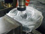
- Parts turned on lathe, purchased, and laser cut
-

- Front bushing and adapter
-

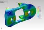
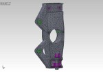
- Finite Element Analysis (FEA) mesh of collapsible steering column joint in frontal impact
-

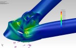
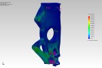
- Finite Element Analysis (FEA) of collapsible steering column joint under maximum torque
-
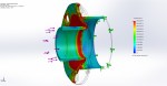
- Finite Element Analysis (FEA) of collapsible steering column joint in frontal impact
-
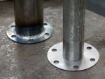
- Collapsible column takes shape. 1mm steel is strong in torsion, weak out of plane.
-

- Collapsible section finished
-

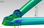
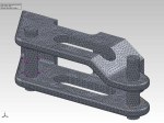
- Finite Element Analysis (FEA) mesh of steering column quick-release adapter to column.
-
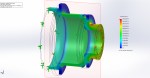
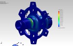
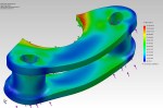
- Finite Element Analysis (FEA) of steering column quick-release adapter to column.
-

- Turning the adapter from column to quick-release
-

- Finished adapter from column to steering wheel quick-release
-

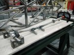
- Parts finished, still need welding
-
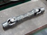
- Welded double U-joint. Note clocking of joints. Important!
-

- Welding the U-joints. Kept cool with wet cloths.
-
- Machining the steering wheel to fit the quick-release.
-
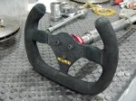
- Steering wheel attached
-
- Column finished