Formula 1000 Race Car First Drive

HelmetCam

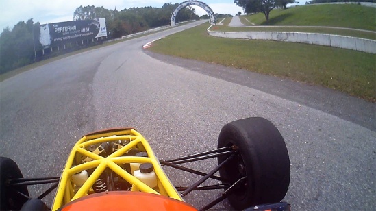
Helmet Cam image from first test at Bira Circuit, Thailand, 11 Aug. 2015 Click for video.

After five long years of work, the car finally made it to the track!

On Tuesday, August 11 we did a shared-track day at Bira International Circuit in Pattaya, Thailand. The trailer’s not finished, nor do I have a tow vehicle yet, so we had a slide truck pick the car up and deliver it to the track. Bira’s only five minutes from my house, so this was easy.

So here we are at the track with a car designed from a clean sheet of paper, a prototype that’s never turned a wheel, a driver who’s ever driven only one lap of this course in a Honda Jazz/Fit several year ago, who’s never driven a sequential transmission, hasn’t been in a race car in 14 years, never driven with race tires, and tires, in fact, that were bought used several years ago. Also, springs and shocks that turned out to be way too stiff, and no front wing, rear wing, sidepods, or diffuser. Yeah! Let’s go!

Surprisingly enough, the test went great! Through various friends I had four mechanics helping me, three of whom were experienced race car mechanics. Before going out the mechanics went over the car carefully and found a small gas leak at the fuel tank and a slight oil leak at the oil pressure sensor, but those were soon fixed. I did one slow lap, starting to bed in the brakes, then came in for a check. Then I did another 8 laps to finish bedding-in the brakes and brought the car in for a complete check. At that point we had to adjust the drive chain tension.

After I rested I went out again for several more laps trying to bring the speed up, doing a best lap around 1:28, still very slow for Bira. I brought the car in when my neck couldn’t take it anymore, after only about six laps. The issue was not so much cornering force as it was the wind pushing my helmet backwards; I just couldn’t hold my head up against it. We found a few issues like the torque spec on the left front wheel bearing was not high enough, leaving the axle free to wobble a bit in the bearing. Also, the left rear lug nut backed off, and the throttle cable came loose at the engine bracket. We increased the lug nut torque spec and reversed all the nuts so the flat side contacted the wheel as we decided the radius on the wheel was too small to properly contact the conical face of the nuts.

For the third run I brought the speed up more, with a best lap of about 1:21, but the car was undrivable at high speed. I believe it was actually bouncing in the air on the straight, as I could hear engine speed variations even when I wasn’t touching the clutch or gear lever. I kind of expected something like this as the springs are way too stiff. Anyway, the stiff springs bent the right rear suspension pushrod adjuster, and we were done for the day.

So overall, the suspension geometry feels perfect. The engine, transmission, electrical system, frame, steering, cooling and almost everything else worked flawlessly.

Wow, it fast! It’s the most amazing thing I’ve ever driven. It makes my old twin-plug 3.5 liter Porsche 930 feel like a tractor. But it demands precision and skill– I felt like an elephant learning to tap dance. As I’m sure you will see from the video, my shifting was all wrong. All the action in the clutch is in the first half inch, whereas the throttle pedal moves like four inches so coordinating the two was difficult. In addition, I was still driving it like a normal transmission, using the clutch on upshifts, as we decided to learn proper sequential shifting in a later test. I can see that with some suspension tuning, aerodynamics, tires, and a software upgrade for the nut that holds the steering wheel, the car will be seriously fast.

Thanks to everyone on Apexspeed who has provided advice, technical knowledge, and emotional support over the years. I couldn’t have done it without you!

 

Designing and Fabricating the Steering Rack Mount

Rack Mount

Steering rack mount, ready to weld gussets.

Next step in getting the car rolling is to mount the steering rack. These parts were not laser cut but were cut with angle grinders and my bandsaw, because they’re, um, a design improvement. Yeah, a design improvement, that’ll work. It took me months to find a blade for my bandsaw, because Thailand. Anyway, now it’s useful for these kinds of tasks.

Once again we have something that looks simple, but took a great deal of thinking to arrive at. As Steve Jobs said, “Simple can be harder than complex: You have to work hard to get your thinking clean to make it simple.” I used to do almost exactly what Steve Jobs did; in fact, he once called my boss to persuade him to cancel the design we were working on, because Jobs was going to do it better (he didn’t). So I understand precisely what Jobs meant about simplicity. That might help explain why this was my fifth complete design for this subassembly. One downside of mechanical design: when you’ve sweated out an elegant design, anybody can take a casual glance at it and say “OBviously”. To which I reply, “OK, there’s probably an even better design out there somewhere. Let’s see you find it.”

Also attached are a few of the finite element analysis (FEA) tests that I performed to verify and improve this design.

Rear Suspension Rocker Arm Mounts & Nose Mounts

Rocker Bushing

Rear suspension rocker arm mount shaft bushing

Above you’ll see that my welding continues to improve, although slowly. In response to the deleted commenter of the day, yes, we do use dyslexic dwarfs to do our welding, but we get ours from Lithuania. Good guess, though!

Next we have photos of the rear suspension rocker arm mounts. As these have to be positioned correctly in three dimensions and three axes, and none of those are X, Y, or Z, it took about a week to get these fabricated and fitted. Starting with laser-cut pieces proved useful as that gave me a known-good shape to start from, but some of the frame rails could be a few millimeters off. Also, every time I weld on something it distorts. Both halves of the rocker arm mounts must be precisely concentric and exactly the correct distance apart. Unfortunately they are not connected directly to each other in order to allow for rocker arm movement between them so there’s plenty of opportunity for them to move, even though I did the welding with the rocker arm shafts in place. In the photo with the control arms installed, you’ll see one answer to that: a long piece of steel rebar turned to fit inside the rocker arm shaft bores. Pounding on that with a rubber mallet would move the bores back into alignment a bit at a time.

Also, nose mounts. In the end these look terribly simple, but it took me a lot of thinking about how to do this. They have to be strong enough in one direction to lift the nose of the car with a pivoting jack, and in the other direction they have to support the downforce of the front wing. Also, they can’t protrude or be sharp so as not to injure another driver in a crash while taking the tremendous force of a forward impact, and have to allow the nose to be adjusted in three dimensions and two axes for proper body fit. Body installation begins here; the rest of the body will be keyed off the nose.

Nose Mounts

Nose attachment points laser cut and welded in place.

Building the Chassis Jigs

Scrap Jigs

First "professional" jigs

Because this looked like a lot of busy work, my first thought was to have the chassis jigs built by a local machine shop. So I bought the metal and had it sent directly to the machine shop and went over the drawings with them. They kept asking me how big various things were, when the dimensions were clearly right there on the drawing. Then it became clear they didn’t know how to deal with dimensions in meters. They asked me how to convert a dimension from meters to centimeters. “You mean like move the decimal point two places to the right?”, I’m thinking… This was not looking promising. Eventually I went home and tried to come up with a set of orthographic-projection drawings, with hidden lines removed, that they couldn’t possibly misinterpret. I soon gave up. When I went to pick up the first two jigs the next day, the list of errors was long and creative. Mounting footprint on one reversed, vertical tube holders cut too shallow and not in line, overall height incorrect, horizontal alignment out of spec, etc., etc.

Sigh. I called a local aerospace-engineer type that I know and asked him if he knew a good machinist, and he directed me to a local guy who I visited the next day. We met a couple of times and he is indeed capable of handling the project; in fact, I decided it’s really below his capabilities and ended up building the jigs myself, saving him for building actual car parts.

Cut Pieces

Lots of cut pieces waiting for welding, drilling, & milling

I needed a good, strong right angle to hold the pieces in place while welding. The bandsaw table served perfectly.

Welding Jig

Welding the angles onto the uprights. Chassis table is very useful here.

Drilling Crossmembers

Drilling the chassis table crossmembers on the milling machine.

Trial Fit

First trial fitting of the chassis jigs onto the chassis table. Top rail guides not yet cut; other tube guides not yet in place.

Welding Verticals

Welding tube guides for vertical tubes. Sample tube keeps things in alignment, along with very careful tack welding.

Jig Set

Almost-finished complete set of chassis jigs

Subframe Pins

Chassis table crossmembers were drilled for pins to hold front subframe during welding.

Stretched Bolt

3/8" bolts should be tight. But not this tight.

Lower Front A-arm Front Attachment Point

Front Suspension Jig Point

Lower Front A-arm Front Attachment Point

The first jig hard point will be the lower front A-arm front attachment point. This may look a little odd if you’re only acquainted with street-car derived race cars, as the lower front A-arms almost meet in a point under the car, much like a Formula 1 flexure. This gives the suspension the optimum geometry for minimal camber change under body roll, and is part of the reason street-car based race cars can’t come close to the performance of a purpose-designed formula race car. The jig attachment point is fabricated from 3″ x 1/4″ steel C-channel, cut to the basic shape with the plasma cutter, ground with an angle grinder closer to its final shape, then the reference faces were milled on the milling machine to an accurate final shape. Then I turned up a small cylinder like the one that will be welded into the chassis, to serve as a spacer to locate the braces when they are welded to the chassis table. In the photo, the braces have not yet been welded to the jig crossmember.

Table Damage

Plasma cutter erodes concrete tabletop

In the process, I learned something not to do with the plasma cutter. I laid the C-channel on a concrete table for cutting, and the plasma stream went straight through a quarter inch of steel and seriously eroded the concrete. Hard to believe this took only seconds to happen!

The plasma cutter is an amazing tool. Cutting through this much steel with a 14″ portable cutoff saw, well, after 15 minutes I gave up. Once you know what you’re doing with the plasma cutter, a cut like this takes only 10-20 seconds.

Plasma Cut Edge

Raw edge cut by plasma cutter


Here’s what the raw cut edge looks like. Those ripples are from the shaking of my hands as I move the cutter. When cutting, you feel no resistance at all, but if you go too fast the cut won’t go all the way through the metal. When first using the plasma cutter, it took me a while before I figured out what I was looking at. The welding helmet has to darken so much, and the plasma is so bright, that you can only see a tiny area around the beam. Eventually I figured out that, if you view from the right angle, you can see the actual beam which is as narrow as a needle. Once you can see it you can control it better.

Welcome to the LudemannEngineering Blog

Greetings! On this blog I’ll be documenting my efforts to bring SCCA-style Formula 1000 racing to Thailand. Formula 1000 is the fastest-growing class of race cars in the Sports Car Club of America, as it provides the greatest excitement for the money, but has not yet been seen in Thailand. Based on 1000 cc superbike engines and transmissions, the cars feature open wheels, slick tires, wings, and ground effects. Cornering speeds and braking are comparable to Formula 1 cars of 25-30 years ago. Costs are kept low by prohibiting engine modifications and exotic materials, and requiring a steel tube frame. The next step up in amateur racing is Formula Atlantic, which costs serious money.

First off is to build the prototype.