Designing the Chassis Jigs

Frame on Jig

Chassis in place on chassis table with all jigs in place

I had been trying to keep the chassis jigs in my head, but finally decided they’d probably come out better if I put them on paper first. So I spent the past few days designing them, and it became quite clear why I couldn’t keep them all in my head. I intend to bend the top chassis rails in one continuous curve as that will add a lot of style to the chassis. A lot of race car frames look like industrial equipment, but I have something in mind more like an Ariel Atom exoskeleton car, where the frame is so beautiful you don’t even need a body. Of course the car will have a body for aerodynamic, esthetic, and safety reasons, but I’d like people to see the frame without the body and still say “Wow!”. Now, the top rails are splines, not just arcs, and the only way to really bend one properly is to know where it’s supposed to be in 3-d space along it’s length, and that’s where the chassis jig comes in. When the chassis jigs are all in place, it will give me target locations all along the length of the frame that I can bend the rail to fit.

I eventually ended up with 22 pages of drawings that look like this:

Sample Jig

1 of 22 chassis jig drawings


And two pages of drawings that look like this:

Cross Rails

Sample chassis jig cross rail drawing

Finished the Swing Set

Finished Swing Set

Slide works and everything!

Chain ladder

Chain ladder up one side of swing set, just for variety

Chain attachment

Chain ladder is attached by welding on a piece of bent 1/4" rebar, flattened on the ends by pounding against an anvil.

Swing seat

Swing seats were made from 1 1/2" hardwood left over from building the house stairs, a 1" radius cut on the outside corners, and rounded off top and bottom with a 1/8" roundoff router bit

Seat Attachment

Chains are attached to seats with 1/4" threaded rod, bent to shape and welded at the top as it was too brittle to make the sharp bend. Carabiners were purchased at a local hardware store.

Seat Bottom

Nuts were welded in place to hold wooden seats on the stirrups. Can't afford a failure in use here.

Swing Chain Attachment

Swing chains were attached same as the chain ladder

Slide Attachment

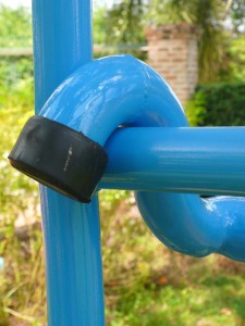
Slide slips over a crossbar of the swing frame. Ends are capped with rubber feet available off the shelf.

Bottom Corner

Bottom crossmembers used square instead of round tubing to spread the load better. Ends were capped with rubber feet available off the shelf. Also welded on tiedown lugs from the local hardware store.

Slide Surface

To make it slippery I sanded the slide with 1000, 1200, and 1500 grit wet-or-dry sandpaper, then polished with two coats of fiberglass mold release wax. It's really slippery.

Free Download: Swing Set Drawing

Swing Set Drawings

Free Download! Children's playground swing and slide set

Just for grins, here are the plans for the children’s swing set and slide in case anyone wants to build one him/herself. Note that I specified the tubing thickness at 1.6 mm, where I built mine with 1.2mm tubing. I felt that it could benefit from being stiffened up a little more. Also not shown on the drawing is the attachment points for the swings and a set of chains up one side of the main structure that form a ladder. I’ll post a photo of the finished project later for reference.

Test Project: Children’s Slide

Frame for slide

Slide frame welded from bent tubing

Wire Support

Chicken wire was welded to the frame and bent into position to hold the fiberglass in place while the resin cures.

Fiberglass Cloth

Fiberglass cloth is cut to size and laid in place.

Resin Applied

Polyester resin is applied

Slide Bottom

Resin cured too fast due to a) no data sheet b) language barrier and c) confused salespeople

Bottom Fiberglassed

After attempting to smooth out the bottom with body putty, I ended up fiberglassing it in for appearance and safety

Slide Puttied

The top of the slide after several layers of 2-part body putty and red glazing putty, sanded and ready for primer.

Primer Applied

Primer applied with spray gun

Bottom Painted

2-part epoxy top coat sprayed on bottom of slide

Top Painted

2-part epoxy sprayed on top. I love this paint (Jotun Penguard Enamel).

Top Close-up

Close-up of finished topcoat, Jotun Penguard Enamel, sapphire blue, 2-part epoxy

World’s First TIG-Welded, Finite-Element Analyzed Swing Set?

Although I originally learned to weld over 30 years ago in college when my team was building a Mini-Baja race car, I never did anything with it as one of the other team members picked it up faster than me and ended up doing all the welding. Welding has changed a great deal since then, so it’s time to relearn anyway. To that end I designed a swing set for my daughters, which I’m building with the same techniques I’ll use to build the Formula 1000 car, including the TIG welder, plasma cutter, tubing bender, and chassis jig table.

Swingset Resonant Frequency

Initial build's fundamental resonant frequency

When I got the initial structure built I found it had a large side-to-side resonant frequency that I measured at 2.50 Hertz. It needed to be stiffened up. Rather than take a guess at how to fix it, with the possibility of several iterations, I decided to do what I should have done in the first place and perform a proper finite-element analysis.

I was pleased to find that the initial FEA results matched reality well, giving a predicted first oscillation mode frequency of 2.72 Hertz.

Then it was a simple matter of trying out a few modified designs and finding one that was functional, cheap, easy to build, and looked good. I tried several forms of bracing but settled on simply adding a slide to one side.

Revised design

Addition of a slide increases natural frequency to 11.2 Hertz

A more elaborate version of the slide had been present in my initial design but had been discarded when I found out how slow I am at welding. The new design’s resonant frequency increased to 11.2 Hz, an increase of over 300%. Indeed, where the frame without the slide felt quite wobbly, with the slide it feels very rigid.

Learning to weld has been… interesting. Although I did find the appropriate pedal control for the TIG welder on Ebay in China, it turns out the pedal doesn’t work the same way as it does on an American-made welder. On a Lincoln TIG welder, for example, you use the front-panel controls to set both the minimum and maximum power and then the pedal moves within that range. On my Chinese welder, the current settings on the front panel are disabled by connecting the pedal and the pedal control range is always from zero to 200 Amps. Maybe this works OK for welding structural steel, but it’s not so wonderful for welding Coke cans. Or race car chassis, for that matter.

Welder Settings

TIG welder settings for 1.2 mm mild steel tubing

So I had to take a step back, disconnect the pedal control, and through trial and error find a way to adapt the Chinese welder to my task. I spent some time poking around the Internet and learned a lot from this a most excellent thread on Race-Dezert.com, authored by one of the Gods of Fabrication. Based on some tips I gleaned from this thread, I switched to the smallest electrode (1 mm) and the smallest filler rod (1.6 mm) that I have. I turned the pulse rate way up to approximately the max of 300 Hertz, although it’s hard to say since there’s no readout, adjusted the pulse duty cycle to 50% and the “basic” current to 50%. At the higher pulse rate the digital readout gives an approximation of the average current instead of continuously changing semi-random numbers within the range like you see at the lower rates. When I nudged this averaged reading up from 60 to 65 Amps, things finally came together.

A weld!

Finally, a proper weld!

I also bought a pair of cheap, strong reading glasses that I can wear under my welding helmet, and once I could see the process close-up and sharp I could make real welds! It turns out that the hot zone isn’t inherently fuzzy, it’s my eyes.

Welding

Apprentice welder at work