Completing the Chain Tensioner, Rear Sprocket & Shift Linkage

Rear Sprocket

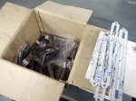
Rear Sprocket in place

Completing the car is now just one long series of small projects. Three are shown here.

The original chain tensioner design was not able to take up enough slack in the chain. The chain was either too short or too long, no matter how many links I used or where I put the adjustment. I had to come up with a new design with two idler sprockets instead of one, as you can see in this post. The bearings are special ceramic hybrids to handle the extreme chain speeds seen with a GSX-R1000 engine.

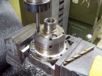
I’ve had a rear sprocket on the car for some time, but that was just for fitting. The lightening holes on that sprocket conflicted with the mounting holes required by the differential, so it wouldn’t have been strong enough. Instead, I ordered a blank sprocket from England and machined the correct mounting holes and center hole, then cut it in half on the bandsaw so that it could be mounted or changed without disassembling the whole rear axle and suspension.

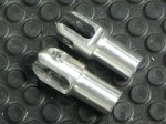
I also built an adapter to go from the auto shift linkage to the transmission gear change lever. I bought a Suzuki GSX-R shift link rod from Ebay, cut off the front, and welded it to a threaded rod. The rod threads into a bushing I made that fits inside the eye of the shift linkage. The sleeve of the shift cable must be held securely, so you can see here the bracket that mounts it to the frame rails.

Youtube Video Update 8

Yet another video update. Here you’ll get a tour around the car pointing out the newest additions, followed by fabricating the fuel swirl pot and mount, the first power-up of the electrical system, mounting components on the instrument panel, drilling the firewall for fuel lines, fabricating braided stainless steel fuel lines, building and installing the throttle pedal cable pull rod and the cable itself, building the ECU mounting platform, and machining the rear sprocket to fit the differential.

Youtube Video Update 8

ECU Platform

ECU mounting platform, with room for more electronics

Swirl Pot

Fuel swirl pot fabricated and mounted

Fabricating the Pedal Cluster

Voila!

Finished pedal cluster

Here’s a big project that spread out over a number of months. I’m aggregated the photos here and attempted to make them tell a coherent story.

The cluster as a whole can be adjusted forward and back for drivers of different heights. The gas pedal is adjustable for foot travel, throttle cable travel and left/right position. The brake pedal height is independently adjustable, and brake bias is adjustable from front to back. The hydraulic clutch pedal is also independently adjustable for height.

Many of the original pieces were laser cut from steel, then bent and welded to form the complex shapes required. Some of the bushings were CNC turned, but most were made by hand. The master cylinders, brake bias adjustment cable, and the nuts and bolts were purchased, with everything else custom made. This includes the brake bias adjustment assembly, which forced me to learn how to cut threads on the lathe. It’s not as easy as it looks. Take a look at the brake bias adjustment bar– it has three sets of threads independently cut on a manual lathe, three diameters, two snap rings and a threaded hole. Good fun! Due to changes in the steering rack mount, the main pedal bracket had to be widened as you can see in the photos.

Computer Rendering

Computer rendering from early 2011

Fabricating the Shifter Assembly & Linkage

Assembled

Assembled shifter mechanism

I looked through a bunch of street car transmission shifter cables, brought a couple of them back to the lab, and decided on one that was the correct length, light, and low friction. Everything else was fabricated…

The car will use a Suzuki GSX-R1000 engine, which has a 6-speed sequential transmission, meaning the shifter only has two movements: shift up, and shift down.

Mounting the Rear Sprocket

Mounted

Rear sprocket mounted on the differential

The limited-slip differential is a torsen or quaife type made by OBX, imported from the USA for an American-style Honda Civic. The differential ring gear on American Honda Civics is mounted with left-hand threaded bolts, so I blithely go down to the auto recycler here in Thailand and buy a differential for donor parts. Hmmmm… these bolts don’t fit. So I check carefully and find these differentials are sold in Thailand with right-hand threads! I go back to the auto recycler and ask for left-hand threaded bolts. They just look at me with that “crazy foreigner” look. OK, all we have to do is order some American-style bolts from Ebay US… There is exactly one listing on all of Ebay, and they don’t ship to Thailand! Plan B: drill the suckers out and use through-bolts.

This is where I find out the differential housing is made of some ultra-hard tool steel, or maybe kryptonite or something. Wow, are these holes difficult to drill out. Solid carbide end mill, highest speed on the milling machine, lots of lubrication, and wait. And wait. And wait…

Next we had to drill a matching hole pattern in the rear sprocket, then cut it in two halves for quick changing at the track. This sprocket will be for static test only as the new hole pattern wasn’t compatible with the old one, leaving thin aluminum in some places. I’ve since ordered a blank rear sprocket from England which I will cut with only the correct holes.

Removable Engine-Compartment Frame Rail

My original plan was to make the engine install from the bottom as I’d owned Porsche 911s for most of my life, but feedback on the ApexSpeed.com forum made me change my mind. The change was fairly simple, requiring only making the upper right engine-compartment frame rail removable. Taking an angle grinder to cut a big chunk out of my finished frame definitely made me measure seven times, cut once.

Fabricating GSX-R1000 Engine Mounts

Sorry for the long delay since the last blog entry. A lot of water has gone under the bridge since then. But don’t worry, the project has continued, although with some big distractions. I’ll be trying to catch up on my blogging in the next few weeks.

Next up is fabricating the engine mounts for the 2007-8 Suzuki GSX-R1000 motorcycle engine. I surveyed the state of amateur formula-car engine mounts, and decided a lot of them are inadequate. This video got me to thinking: https://www.youtube.com/watch?v=m1j7hmJmSJA as my car should be faster than a Ferrari 458. Some might be skeptical of that speed comparison; if you are, take a look at this comparison of a Porsche 911 Turbo versus a formula 4 car: https://www.youtube.com/watch?v=e8WyvVbVu4k . A formula 1000 car should compare favorably with a formula 4 car. Either way, you lose a lot of torsional rigidity with the large open hole to mount the engine, and I hope to recover much of that with a strong triangulated set of engine mounts.


Turning the Steering Rack Extensions

The ends of the steering rack have to be in line with a plane through the control arm attachment points, and unless you have a custom-made rack this will require extensions to each end of the rack. I got these made and then went to the local nut & bolt emporium, only to find they don’t carry 3/8-24 socket-head cap screws. I know, weird huh? Had to order them on Ebay in the US and am now keeping my fingers crossed that they will arrive (at all). I recently ordered some more left-handed nuts the same way and they arrived in eight days with no problems, so yay?

For these I had to dig into my precious stash of 7075 aluminum…

Modifying the Wheel Hubs & Axles

We’re using Honda Civic wheel hubs, wheel bearings, CV joints and axle halfshafts. They’re available everywhere, cheap, and light, and by using them we avoid having to cut matching pairs of splines. The wheel hubs are drilled for lightness and tapped to accept the wheel drive pins, then the two outermost pieces from two scrap CV joints are cut down to use as bearing retainers for the front wheels. Rear axle halfshafts are used in stock form, but extenders from the halfshafts to the differential will have to be fabricated later.

When cutting the CV joints I found that the contact faces are hardened some way into the joint, making cutting almost impossible (by which I mean “impossible”) beyond a certain point, even with carbide cutting tools. If they are heat-treated, maybe there’s some way to reverse the hardening? It’s probably something more exotic than that, though, as the hardening was highly location-specific.

Fabricating the Pushrods & Upper A-Arms / Wishbones / Control Arms

Finished

Finished set of control arms, tierods & pushrods

The upper control arms are all identical except that the bearing cups are mirrored from the left to the right so that the snap rings are on the bottom. If I can find a way to stake the spherical bearings then all four could be identical. Staking is a process that uses a hydraulic press to deform the bearing cup into a chamfer around the circumference of the spherical bearing, holding it permanently in place.

I printed out the layout of both control arms onto size A0 paper, glued the paper to a sheet of plywood, and drilled holes for the centerlines of each rod end and spherical bearing. This gives me a jig I can use for tack welding the parts in place. Washers under the bearing cups locate them vertically for tacking. The bearing cups proved a little too thin to weld without distortion, so I had to re-cut the spherical bearing bores after welding. Luckily I have an indexable end mill of just the right diameter, and running my mill at high speed with a lot of coolant gave a good finish on the bores. I then pressed the spherical bearings into place before painting as I wanted to make sure there were no glitches that would require messing up the paint to fix.

I sprayed Jotun Penguard 2-part epoxy paint directly onto the steel after first making sure the steel was scrupulously clean with a Scotchbrite pad on an angle grinder, followed by a cleaning with acetone and paper towels. The finish came out beautifully.