Completing the Chain Tensioner, Rear Sprocket & Shift Linkage

Rear Sprocket

Rear Sprocket in place

Completing the car is now just one long series of small projects. Three are shown here.

The original chain tensioner design was not able to take up enough slack in the chain. The chain was either too short or too long, no matter how many links I used or where I put the adjustment. I had to come up with a new design with two idler sprockets instead of one, as you can see in this post. The bearings are special ceramic hybrids to handle the extreme chain speeds seen with a GSX-R1000 engine.

I’ve had a rear sprocket on the car for some time, but that was just for fitting. The lightening holes on that sprocket conflicted with the mounting holes required by the differential, so it wouldn’t have been strong enough. Instead, I ordered a blank sprocket from England and machined the correct mounting holes and center hole, then cut it in half on the bandsaw so that it could be mounted or changed without disassembling the whole rear axle and suspension.

I also built an adapter to go from the auto shift linkage to the transmission gear change lever. I bought a Suzuki GSX-R shift link rod from Ebay, cut off the front, and welded it to a threaded rod. The rod threads into a bushing I made that fits inside the eye of the shift linkage. The sleeve of the shift cable must be held securely, so you can see here the bracket that mounts it to the frame rails.

Mounting the ECU

ECU Mount

Finished ECU mount

I was lucky enough to find some 7075-T651 aircraft aluminum plate, still with the Martin Marietta markings on it. Very useful for miscellaneous parts like this ECU mount. That stuff is strong! Almost as hard to bend as steel, but it makes for a very stiff end result. So I just cut this blank out of the aluminum plate, bent it in my hydraulic press, and added lightness using the milling machine. It mounts to the frame with aluminum clamshell mounts purchased on Ebay.

Youtube Video Update 8

Yet another video update. Here you’ll get a tour around the car pointing out the newest additions, followed by fabricating the fuel swirl pot and mount, the first power-up of the electrical system, mounting components on the instrument panel, drilling the firewall for fuel lines, fabricating braided stainless steel fuel lines, building and installing the throttle pedal cable pull rod and the cable itself, building the ECU mounting platform, and machining the rear sprocket to fit the differential.

Youtube Video Update 8

ECU Platform

ECU mounting platform, with room for more electronics

Swirl Pot

Fuel swirl pot fabricated and mounted

Building the Axle Halfshaft Extensions


Rear Suspension

Rear suspension, axles and differential in place

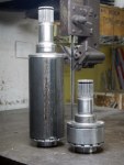
The car will use standard Honda Civic axle halfshafts, and I had the choice of cutting, sleeving and re-welding them, or building extenders that effectively widen the differential to meet the unmodified halfshafts. The cut/sleeve/re-weld option would eliminate the axle hardening and leave unknown strength, and I’ve since seen an example where this was done and the axle broke right at the weld. The option of “widening” the differential has several advantages. First, we can easily replace the halfshafts if necessary in the future with off-the-shelf parts. Second, moving the inner constant-velocity joint closer to the plane of the control-arm pickup points minimizes the plunge, or change in length, required as the suspension moves through its travel. Third, the halfshafts become equal length, eliminating torque steer. Now you may say “but, the extensions will be of different length and will twist unevenly so the torque steer won’t be eliminated”. The extensions will be much stiffer than the axle shafts so that won’t be the case.

So the choice was clear. We started with a differential and a couple of halfshafts as raw material…


Building a Workshop Gantry Crane

I need to be able to lift the engine into the chassis, but due to the lowered floor of the work area a standard engine lift won’t work. While I’m at it, it would be nice to be able to lift the entire assembled car off the build table, turn it ninety degrees, move it to the door, and roll it out of the shop. Below is the solution. Sorry there aren’t any plans. The build process was “go to your local metal recycling center, buy some scrap beams, clean them up, cut them as necessary, and weld them together”. I’m getting more comfortable with winging it in the machine shop.

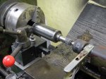
Also shown below is a mount I built to mount an angle grinder on the lathe. Parting-off has always been a problem. I’m just about to make the engine mounts, requiring at least 36 cutoff operations, and I figured I’d better solve the problem. I have a cutoff tool but only purchased a small number of carbide inserts; the inserts wear out really fast and I either have to order more from the US or drive at least an hour to a store that MIGHT have them. This baby works great, giving a clean straight cut. Just have to be careful not to let the abrasive get into the lathe.

Steering Column Supports

Next up: mount the steering column in the chassis. Nothing magical here, just lots of little steps. The steel bearing cup insert did work well at preventing distortion during welding. To get a proper press fit for the rear support bearing I decided to use my new internal bore gauge. At first it didn’t work at all (made in China, of course), so I had to disassemble it completely, figure out how it was supposed to work, unstick the rusted shaft, replace the dead battery, and reassemble it. All in a day’s work out here on the frontier. So now I can measure both holes and shafts to a few microns and press fits are much easier to make.

Fabricating the Steering Column

I originally sent all these parts out to the CNC shop, but they never got back to me with a quote so I ended up making everything myself. The spline onto the steering rack was a tight press fit, so for now the entire column including the rack is a single assembly. I don’t know it’s possible to remove the rack later, and I’m not going to try as it might destroy the rack. The U-joints are special units from Sweet Manufacturing in the US, but don’t seem to be anything special. In the future I might try to adapt standard Honda steering column U-joints and column splines. These use a perpendicular pinch bolt so the column can be disassembled at each joint.

Modifying the Wheel Hubs & Axles

We’re using Honda Civic wheel hubs, wheel bearings, CV joints and axle halfshafts. They’re available everywhere, cheap, and light, and by using them we avoid having to cut matching pairs of splines. The wheel hubs are drilled for lightness and tapped to accept the wheel drive pins, then the two outermost pieces from two scrap CV joints are cut down to use as bearing retainers for the front wheels. Rear axle halfshafts are used in stock form, but extenders from the halfshafts to the differential will have to be fabricated later.

When cutting the CV joints I found that the contact faces are hardened some way into the joint, making cutting almost impossible (by which I mean “impossible”) beyond a certain point, even with carbide cutting tools. If they are heat-treated, maybe there’s some way to reverse the hardening? It’s probably something more exotic than that, though, as the hardening was highly location-specific.

Fabricating the Seat Bottom

Just a quick update here as the next one will be big and I want to keep it together as one post. I want to get all the tabs and brackets attached to the frame as soon as possible so I can paint it, so I started with an easy one: the seat bottom. I had the pieces laser cut, but the shop forgot that there are two identical side pieces and I had to cut that one by hand. I turned out to be easy after making a paper template. Each of the four pieces is a section of a cylinder and some of the edges intersect off-axis with frame tubes, so those lines that look straight really aren’t. The seat bottom is curved like this to get the driver as low as possible, mainly to keep the top of the main roll hoop as low as possible. The curvature was easy to make by just bending the steel by hand and fitting it by eye to the frame.

Attachment points are carefully spaced more than six inches from each other to comply with the F1000 rule outlawing stressed panels (with certain exceptions). It would have been much easier to just weld each piece to the frame tubes below it, but I don’t plan on this counting as the stressed belly pan. A stressed belly pan will be added to the planar bottom of the car. Making the seat bottom removable gives the advantage of easier access to the triangular compartment below it for mounting the fire extinguisher and whatever else will fit, and I can also replace the seat bottom later with a carbon fiber and kevlar version to save weight. At the moment I’m appreciating the fact that certain important body parts will be protected by two layers of steel in the event of a crash.

Designing and Fabricating the Steering Rack Mount

Rack Mount

Steering rack mount, ready to weld gussets.

Next step in getting the car rolling is to mount the steering rack. These parts were not laser cut but were cut with angle grinders and my bandsaw, because they’re, um, a design improvement. Yeah, a design improvement, that’ll work. It took me months to find a blade for my bandsaw, because Thailand. Anyway, now it’s useful for these kinds of tasks.

Once again we have something that looks simple, but took a great deal of thinking to arrive at. As Steve Jobs said, “Simple can be harder than complex: You have to work hard to get your thinking clean to make it simple.” I used to do almost exactly what Steve Jobs did; in fact, he once called my boss to persuade him to cancel the design we were working on, because Jobs was going to do it better (he didn’t). So I understand precisely what Jobs meant about simplicity. That might help explain why this was my fifth complete design for this subassembly. One downside of mechanical design: when you’ve sweated out an elegant design, anybody can take a casual glance at it and say “OBviously”. To which I reply, “OK, there’s probably an even better design out there somewhere. Let’s see you find it.”

Also attached are a few of the finite element analysis (FEA) tests that I performed to verify and improve this design.