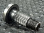
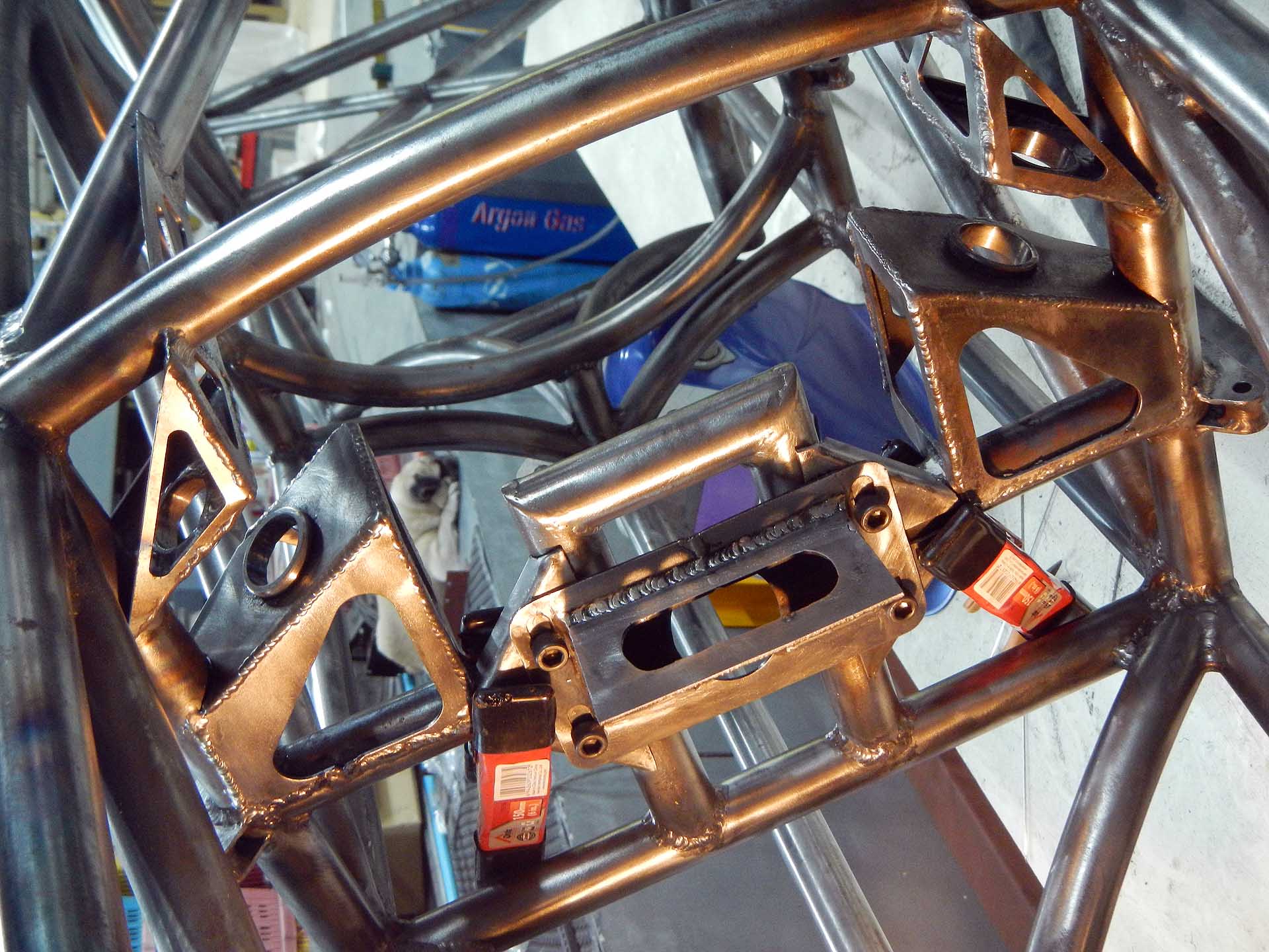
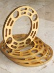
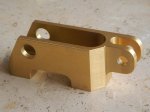
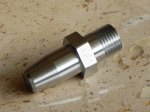
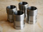
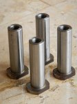
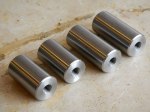
Rear suspension rocker arm mount shaft bushing
Above you’ll see that my welding continues to improve, although slowly. In response to the deleted commenter of the day, yes, we do use dyslexic dwarfs to do our welding, but we get ours from Lithuania. Good guess, though!
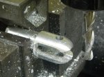
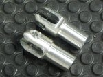
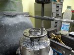
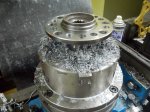
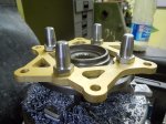
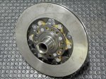
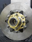
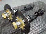
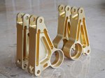
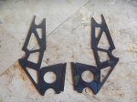
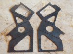
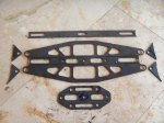
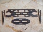
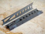
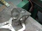
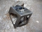
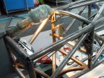
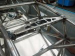
Next we have photos of the rear suspension rocker arm mounts. As these have to be positioned correctly in three dimensions and three axes, and none of those are X, Y, or Z, it took about a week to get these fabricated and fitted. Starting with laser-cut pieces proved useful as that gave me a known-good shape to start from, but some of the frame rails could be a few millimeters off. Also, every time I weld on something it distorts. Both halves of the rocker arm mounts must be precisely concentric and exactly the correct distance apart. Unfortunately they are not connected directly to each other in order to allow for rocker arm movement between them so there’s plenty of opportunity for them to move, even though I did the welding with the rocker arm shafts in place. In the photo with the control arms installed, you’ll see one answer to that: a long piece of steel rebar turned to fit inside the rocker arm shaft bores. Pounding on that with a rubber mallet would move the bores back into alignment a bit at a time.
-

-
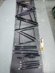
Positioned and held in place with bungee cords, ready for welding
-

-
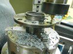
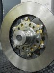
Welding finished
-

-
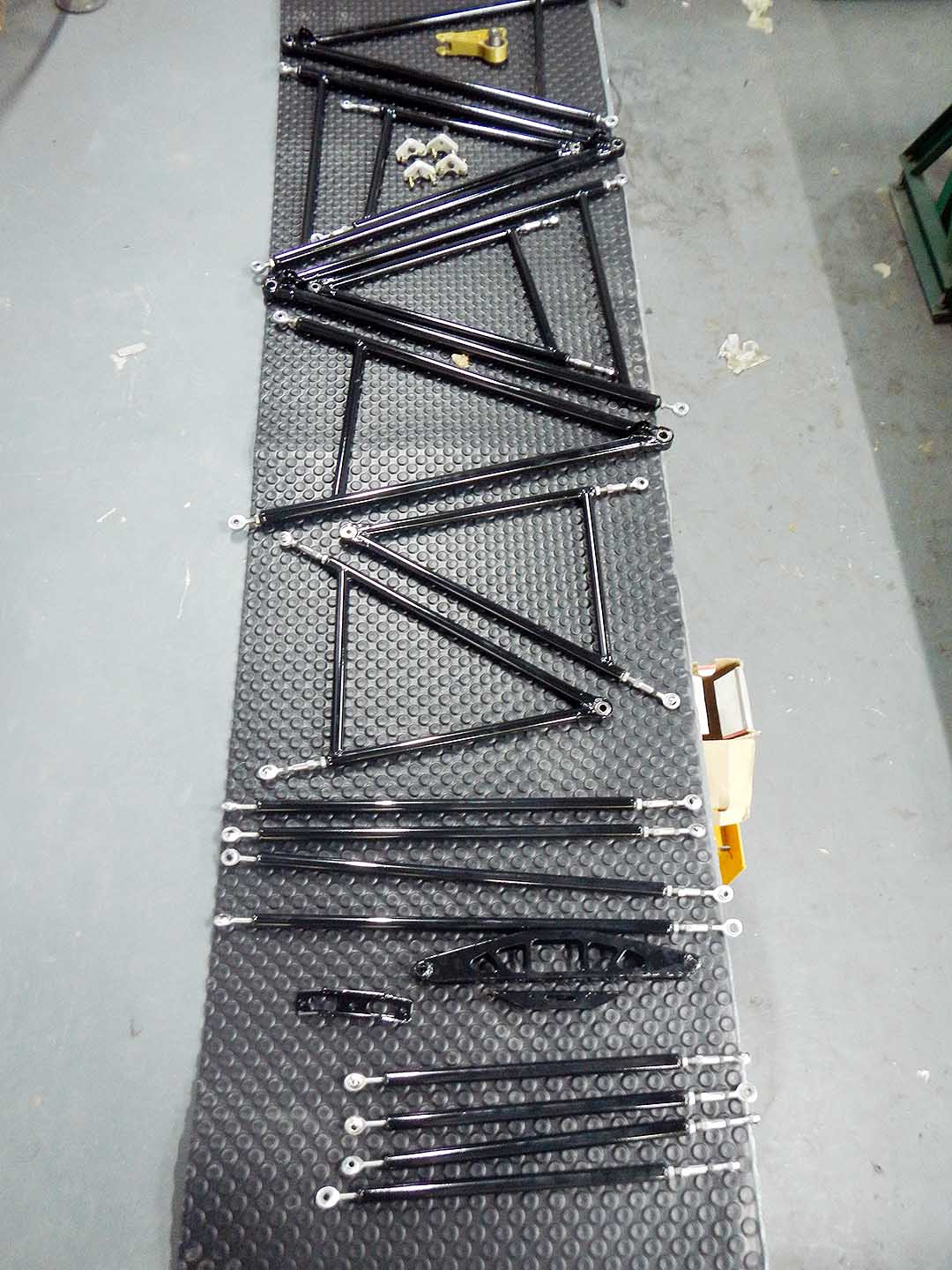
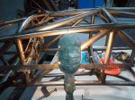
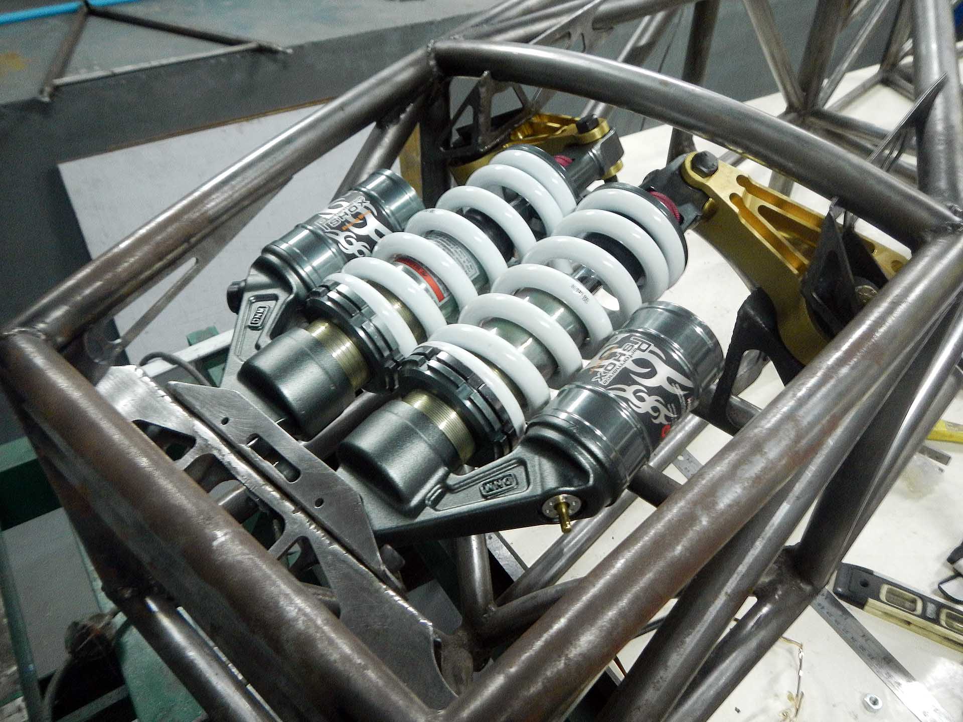
Control arms, springs, shocks & rocker arms installed for the first time
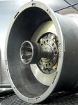
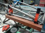
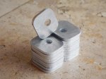
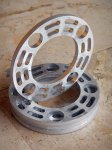
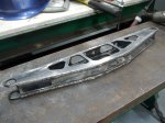
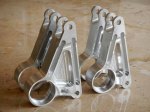
Also, nose mounts. In the end these look terribly simple, but it took me a lot of thinking about how to do this. They have to be strong enough in one direction to lift the nose of the car with a pivoting jack, and in the other direction they have to support the downforce of the front wing. Also, they can’t protrude or be sharp so as not to injure another driver in a crash while taking the tremendous force of a forward impact, and have to allow the nose to be adjusted in three dimensions and two axes for proper body fit. Body installation begins here; the rest of the body will be keyed off the nose.

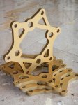
Nose attachment points laser cut and welded in place.