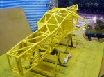
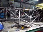
Formula 1000 race car floorpan with front keel
In my continuing effort to get everything welded onto the frame so can paint it, it’s time to build the floor pan. SCCA rules allow the floor pan to be a stressed skin, so this one fully welded around outside and to all crossmembers. To anyone who wants to learn to weld better, I recommend welding a floorpan. That’s a lot of welding. None of these pieces were laser cut– templates were made in plastic sheeting, transferred to sheet steel, and cut out with an angle grinder. Wear hearing protection. And eye protection. And lung protection. And heavy gloves up to your elbow. Angle grinders can mess you up.
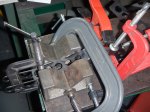
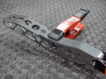
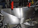
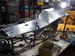
The floor pan around front keel is of special interest. Some parts have a single curve which is easily fabricated, but two of the pieces have a compound curve which can’t just be bent. They have to be pounded into submission to make them fit. As this is my first attempt at metal shaping, I started out tentatively. After a lot of pounding I was getting nowhere and got angry. It turns out this is what you need to do. Pound the crap out of it, then fix the area around the big dent you just made, and eventually it takes shape. An English wheel would have been useful, but building or buying one is a big project.
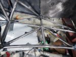
There are two layers of steel under the fuel tank and the driver’s butt, one under the legs. Should be stiff, strong, and safe. And now, on to the photographs. I suffered through this. Now it’s your turn:
-
-
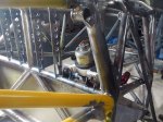
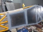
Priming the bottom of the fuel tank
-
-
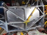
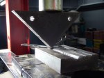
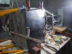
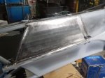
Fuel tank cover clamped in place
-
-
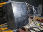
Fuel tank cover welded
-
-
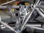
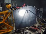
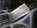
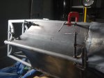
Engine compartment cover clamped in place
-

-
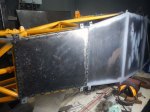
Driver’s butt cover clamped in place
-

-
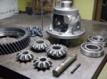
Differential cover clamped in place
-
-
Differential cover tack welded
-
-
Differential cover finished
-

-
Plastic templates transferred to steel sheet
-
-
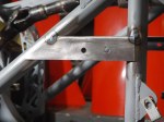
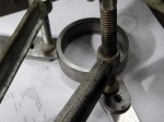
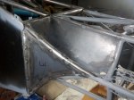
Right front keel transition; compound curve
-
-
Right Front keel transition finished
-

-
RF Keel
-
-
Left Front keel transition as a flat sheet
-

-
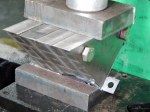
LF Keel transition pounded into submission
-

-
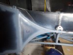
LF keel transition stitch welded
-

-
LF keel transition finished
-
-
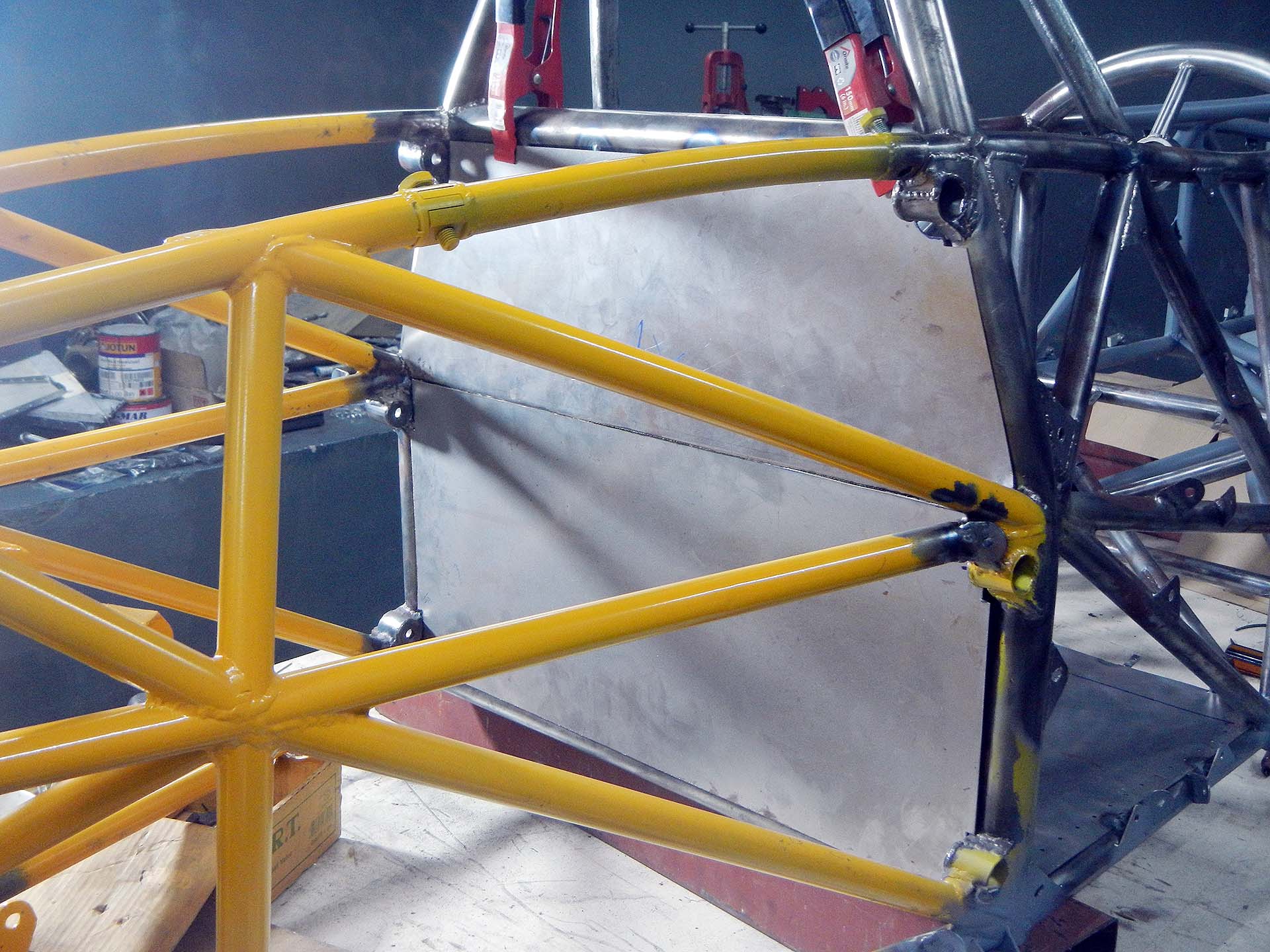
Left Front keel clamped in place
-
-
LF keel finished
-

-
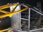
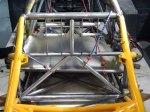
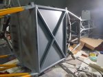
Finished floor pan