Yet another video update. Here you’ll get a tour around the car pointing out the newest additions, followed by fabricating the fuel swirl pot and mount, the first power-up of the electrical system, mounting components on the instrument panel, drilling the firewall for fuel lines, fabricating braided stainless steel fuel lines, building and installing the throttle pedal cable pull rod and the cable itself, building the ECU mounting platform, and machining the rear sprocket to fit the differential.
Category Archives: Cutting
Building a Workshop Gantry Crane
I need to be able to lift the engine into the chassis, but due to the lowered floor of the work area a standard engine lift won’t work. While I’m at it, it would be nice to be able to lift the entire assembled car off the build table, turn it ninety degrees, move it to the door, and roll it out of the shop. Below is the solution. Sorry there aren’t any plans. The build process was “go to your local metal recycling center, buy some scrap beams, clean them up, cut them as necessary, and weld them together”. I’m getting more comfortable with winging it in the machine shop.
Also shown below is a mount I built to mount an angle grinder on the lathe. Parting-off has always been a problem. I’m just about to make the engine mounts, requiring at least 36 cutoff operations, and I figured I’d better solve the problem. I have a cutoff tool but only purchased a small number of carbide inserts; the inserts wear out really fast and I either have to order more from the US or drive at least an hour to a store that MIGHT have them. This baby works great, giving a clean straight cut. Just have to be careful not to let the abrasive get into the lathe.
- Here’s what the overhead beam looked like when I started.
- Drilling holes to mount the wheels. Milling machine makes this easy.
- Welding the uprights to the wheel supports
- Thick steel is so much easier to weld.
- Welding the uprights to the overhead beam, upside down. C-channel is temporary, so it doesn’t fall over.
- Finished. Trolley and chain hoist bought at Hardware House, Rayong.
- So easy, even our spokesmodel can do it.
- Test lifting the chassis. Easy!
- Building adapter to lift the engine.
- First lift of the engine.
- While we’re building tools, here’s a holder to mount the angle grinder on the lathe.
- Parting off has always been a problem. Not anymore. Plastic is to keep abrasive off lathe.
Steering Column Supports
Next up: mount the steering column in the chassis. Nothing magical here, just lots of little steps. The steel bearing cup insert did work well at preventing distortion during welding. To get a proper press fit for the rear support bearing I decided to use my new internal bore gauge. At first it didn’t work at all (made in China, of course), so I had to disassemble it completely, figure out how it was supposed to work, unstick the rusted shaft, replace the dead battery, and reassemble it. All in a day’s work out here on the frontier. So now I can measure both holes and shafts to a few microns and press fits are much easier to make.
- Front bushing; sheet metal cut on bandsaw and with die grinder
- Front bushing support bent to shape
- Front bushing support cap, ready to weld
- Finished front bushing support
- Turning steering column rear bearing cup
- Finished rear bearing cup
- Finished rear column support parts
- Steel insert bushing to prevent distortion of the bearing cup during welding
- Rear support, ready for welding. Note steel insert to prevent distortion.
- Test fit; fit was perfect first try.
- Rear support welded
- Ready to tack weld in place
- Tack welded
- Quality Control Inspector gives her approval.
Designing and Fabricating the Steering Rack Mount
Next step in getting the car rolling is to mount the steering rack. These parts were not laser cut but were cut with angle grinders and my bandsaw, because they’re, um, a design improvement. Yeah, a design improvement, that’ll work. It took me months to find a blade for my bandsaw, because Thailand. Anyway, now it’s useful for these kinds of tasks.
Once again we have something that looks simple, but took a great deal of thinking to arrive at. As Steve Jobs said, “Simple can be harder than complex: You have to work hard to get your thinking clean to make it simple.” I used to do almost exactly what Steve Jobs did; in fact, he once called my boss to persuade him to cancel the design we were working on, because Jobs was going to do it better (he didn’t). So I understand precisely what Jobs meant about simplicity. That might help explain why this was my fifth complete design for this subassembly. One downside of mechanical design: when you’ve sweated out an elegant design, anybody can take a casual glance at it and say “OBviously”. To which I reply, “OK, there’s probably an even better design out there somewhere. Let’s see you find it.”
Also attached are a few of the finite element analysis (FEA) tests that I performed to verify and improve this design.
- FEA result: upper tube compression
- FEA result: suspension rocker arm force
- FEA result: steering rack in 100G bump
- FEA result: 1000 pound steering force
- Complete set of parts hand cut
- Subassemblies welded
- Welding finished
- Bracket installed
Custom Radiator, Lathe Cooling, Suspension Progress
Time for a few miscellaneous updates.
I was always dreading having to machine steel. I had to do it slowly to keep the temperature down and avoid chatter, even though I use carbide cutter inserts. Then I read somewhere that home hobbyists tend to be afraid to run the lathe & milling machine at high enough RPM to keep the cutting inserts happy, but if they do it will cause the insert to overheat and be cooked in two seconds. I figured I can find the cojones to run my equipment at maximum speed as well as the next guy…
So one day I was browsing at my new favorite store, Hardware House in Rayong, and I saw a gallon container of cutting coolant fluid for sale. I’d had no idea of how to find this stuff in Thailand, or even how to ask for it, so it was pure luck to stumble over it. Or you could call it diligence in going up and down every aisle in Hardware House looking for things I might need. They also had flexible fluid squirters and 12-volt water pumps, so I put together my own fluid cooling system, pictured above. I drive the pump with an automotive battery charger which allows me to reduce the voltage and amperage to get the correct flow, and it works like a charm! Now I can cut steel like I used to cut aluminum.
- I found a local place that builds custom radiators for less than I paid for a used one on Ebay in the US.
- Custom-built radiator, rear view
- Positioning the front upper A-arm mounts
- Positioning the rear upper A-arm mounts with jig
- Pressing the suspension rocker arm bearings into place with my homemade press
- Finished suspension rocker arm
Fabricating the Lower A-arms
No, I haven’t just been sitting around the house eating chocolate, but a major malfunction in my main computer leaves me time to update the blog and get caught up on other things I should have done, like taxes. Unlike EVERY OTHER COUNTRY IN THE WORLD (except the Phillipines), even though I haven’t set foot in the USA in over four years, I still have to pay US taxes. The bright side is that California no longer considers me a resident so I don’t have to pay California taxes anymore, which is quite reasonable given that I moved out 11 years ago.
I made the mistake of turning the computer off overnight to help save the planet and all, and the next day it kept dying like someone pulled the plug. Computer shop says I need a new motherboard and graphics card, and oh, by the way, there are no new LGA 1366 motherboards for Intel i7 CPUs in Thailand and the old one will take about a month to fix under warranty. Which is understandable, given that Intel stopped making LGA 1366 i7 CPUs ages ago! Oh wait, they still make them? Or maybe not, from Intel’s website I can’t tell. At least Gigabyte’s warranty will cover their product, or maybe I just haven’t heard what their fine-print objection will be, yet. Azus, on the other hand, says my graphics card is corroded, and corrosion isn’t covered under warranty. Great plan! Make a product that corrodes, then say corrosion isn’t covered. It might be more honest to say “No Warranty”, though. The Azus graphics card was inside a warm computer (which was _almost_ never power-cycled) in an office environment for it’s entire life. Azus is now on my Deferred Vendor List.
Anyway, on to fabricating the lower A-arms, or control arms:
- Starting with the spherical bearing cups, face and cut outside diameter
- Cutting the internal diameter on a bearing cup. This is a press fit, so it has to be cut as perfectly as the tools will allow.
- My boring bar won’t fit into my new quick-change tool holder, so I had to cut it down to fit.
- Boring bar now fits into tool block.
- Cutting the groove for a snap ring. I wasn’t sure I could get the press fit perfect, so I included provisions for a snap ring
- Snap ring in place for a trial fit.
- Using the cutoff tool to cut the part off the stock
- Bearing cup, spherical bearing, snap ring, and ID gauge for cup. I don’t have an internal micrometer, so used my external micrometer to cut a gauge to the precise length for the ID.
- I ground a carbide cutting tool for the boring bar to the correct width to cut the snap ring groove. It took a lot of grinding. Carbide is really hard!
- Starting the rod end receptacles that will be welded to the legs of the A-arms. Face and cut OD on lathe.
- Cut step to fit inside A-arm tube.
- Use center drill for accuracy.
- Drill hole to be tapped for rod end
- Using cutoff tool to part off
- Tap for 3/8-24 left hand threads. A later version of the A-arms may have easy rod-end adjusters, so I’m using left hand threads here, too.
- Cutting a chamfer on the face of the rod-end receptacle. Looks better, is lighter.
- Four finished rod-end receptacles
- Setup for tack welding rod end receptacle into A-arm tube
- Tack welded in place
- Welded all the way around. Holding the tube in a V block makes it easy to turn while welding
- Made 2 aluminum bushings to fit inside the bearing cup and locate it on the jig
- Rod ends are held in jig for welding.
- A-arm jig is made from printed drawing glued to plywood.
- Spherical bearing cup fully welded to one leg of an A-arm
- Both legs of an A-arm fully welded to a bearing cup
- A-arm bearing cup braces marked and cut
- Bearing cup braces in place and welded
- Pushrod mount in place and welded. These pieces were made with the patented (not patented!) technique of printing on sticker paper, cutting with a plasma cutter, grinding to exact shape.
- Spherical bearing is pressed into place on my home made hydraulic press. Custom bushings were made to only push on the correct places, like not the ball.
- Anti-intrusion bar test fitted
- Anti-intrusion bar fully welded. Weld shrinkage is a problem here.
- Welding distorted the bearing cap enough that I had to recut the bore. First, find the center of the hole.
- Next, use a boring head to cut the hole to exact dimension. Very tricky; had to use 1/2 the smallest tick mark on the boring head. Total overlap for press fit is around 0.001″
- Repeat everything four times. Final result: four lower A-arms
Building a Simple Hydraulic Press
I’ll be needing a press to insert the spherical bearings into the control arms and to insert the wheel bearings into the suspension uprights, so I took a couple of hours and built a simple hydraulic press. It’s just a strong steel frame that will give a small 5-ton hydraulic car jack something to push against. It’s taller than it is wide to be able to press items of different sizes by turning the frame on its’ side. Regarding painting, I’m finding that, with modern paints, I don’t need to use primer. I just clean the metal with a wire brush on a variable-speed angle grinder, clean it again with acetone and paper towels, then spray the topcoat on directly. This gives a thin, hard coat that sticks well.
- 4 x 2 x 1/4″ C-channel steel marked for cutting with the plasma cutter
- Plasma cutter makes short work of cutting this thick steel. Each cut would take more than 1/2 hour on a 12″ abrasive cutoff saw, but takes just seconds with the plasma cutter.
- Jigged and clamped, ready for welding
- After welding
- After painting
- Crushed a few things to test it. Can exert some pretty good force.
Making Chips… Finally!
It seems that other people who’ve built cars from scratch attempt to get their cars rolling on the ground as soon as possible, so I figure I’ll do it that way too. With that in mind, it’s time to start fabricating the suspension. First up: lower suspension attachment clevises. I ordered 7075 aircraft aluminum from the United States as part of my big shipment. It’s amazing stuff– stronger than steel but light as aluminum. These assemblies have to be extremely strong, as I calculate that under braking the front one takes a load of over 4400 pounds.
- Start with a solid chunk of 7075 aircraft aluminum, here scribed for cutting slightly oversize
- Blanks are cut to size with thinnest abrasive cutting blade in high-speed angle grinder. I tried using a 12″ cutoff saw, but it couldn’t cut this high-strength aluminum.
- Finished raw blank
- Facing both sides of the blank with carbide-insert face cutter end mill
- Milling holes for bolts to attach to chassis. PDF drawing printed on sticky paper at 1:1 eases the layout and provides a useful double-check against errors.
- Milling the first outside radius on the rotary table.
- Milling the second outside radius
- 45-degree faces are rough cut with the angle grinder, then clevises are supported on V-blocks clamped to the milling machine.
- 45-degree faces milled smooth with face cutter
- Repeat eight times. Ready for slot milling.
- Milling the slots for the rod ends using a ball-end mill.
- Milling holes for the rod-end retaining bolts
- Milling an additional relief for the rod ends. Test assembly showed interference, so I went back to the computer model and, sure enough, there it was. Now I know to use the interference and clearance detection tools.
- Finished lower A-arm clevises. Outside radius on front was also cut on the rotary table / milling machine.
- Lower suspension attachment clevis assembly drawing
Modifying the Lathe Quick-Change Toolpost
So I imported this quick-change tool post for my lathe, which appears to be some kind of standard, but a standard that my lathe just doesn’t happen to abide by. I needed a large (~1 1/2″) hole in the bottom of this solid tool-steel block. I tried drilling it with a carbide-insert drill, but after several minutes had made a cut so shallow it could only be felt by dragging a fingernail across it. After watching a few Youtube videos, though, I decided it must be possible and came up with the setup below, a solid carbide end mill slowly enlarging the hole on a rotary table. The mill left an amazingly high-quality finish.
- New Aloris quick-change lathe tool post mounted upside-down on the rotary table on the milling machine, being cut with a solid carbide end mill.
- Finished hole as cut. Note mirror-like quality from solid-carbide endmill
- Aloris quick-change toolpost in place on lathe after modification, a selection of quick-change toolholders in boxes in background.
Contents: 1 Race Car Kit, some assy. req’d
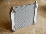
I’ve been accumulating parts for almost the past two years in a warehouse in Los Angeles as it’s easier to buy things in the US and ship them all the way to Thailand than it is to just buy them in Thailand. Also, I only wanted to navigate Thai customs one time. Finally gave them the go-ahead to ship, and a few weeks later everything arrived at my door. Includes just about everything that I can’t make myself or buy in Thailand: wheels, brake calipers, brake discs, brake pads, master cylinders, Aeroquip tubing and fittings, torsen differential, rear axles, spherical bearings, bearings, rod ends, 2007 Suzuki GSX-R1000 engine, crash padding, radiator, oil cooler, kevlar, vacuum-bagging materials, vacuum pump, Halon fire system, and more. Also, everything I need to fully fit out my machine shop, like a rotary table, angle table, and cutting tools. Better than Christmas!
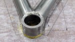
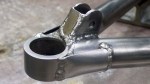
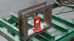
Some assembly required. May require common household items such as tape, scissors, stapler, lathe, milling machine, and TIG welder.
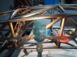
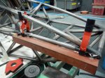
- Race car kit, somewhat the worse for wear after storage of up to two years and trans-Pacific shipping.
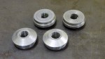
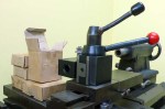
- Some of the parts: centerlock OZ Racing wheels, 13×8″ and 13×10″
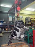
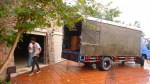
- Truck carrying goodies