Building the Front Wing & Mounts

Front Wing

Finished front wing on the car (endplates to be added after setting ride height)

Drawing: Overall Dimensions

Top Dimensions

Formula 1000 race car top view overall dimensions

I’ve been getting requests for the dimensions of the car from around the world. This should help. Some of the aerodynamic details have changed since this 3D model was made, so don’t take this drawing too literally. If you click on the image above you’ll get a PDF file with both top and side views dimensioned and in high resolution.

Fabricating a Formula 1000 Race Car Diffuser

Diffuser

Finished diffuser mounted on car

I try to post updates only for completed projects, and since I’ve had several projects in progress it’s been a while since I’ve blogged. The diffuser is finally finished, so here are some pix and a video that explains it all:


Formula 1000 Race Car First Drive

HelmetCam

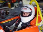
Helmet Cam image from first test at Bira Circuit, Thailand, 11 Aug. 2015 Click for video.

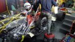
After five long years of work, the car finally made it to the track!

On Tuesday, August 11 we did a shared-track day at Bira International Circuit in Pattaya, Thailand. The trailer’s not finished, nor do I have a tow vehicle yet, so we had a slide truck pick the car up and deliver it to the track. Bira’s only five minutes from my house, so this was easy.

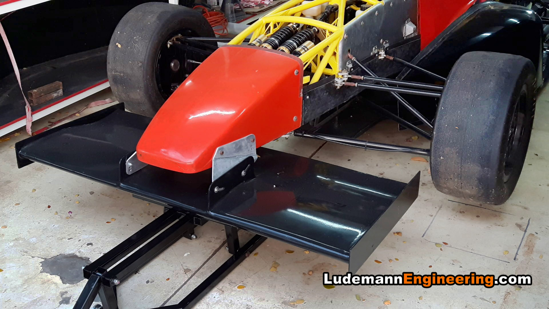
So here we are at the track with a car designed from a clean sheet of paper, a prototype that’s never turned a wheel, a driver who’s ever driven only one lap of this course in a Honda Jazz/Fit several year ago, who’s never driven a sequential transmission, hasn’t been in a race car in 14 years, never driven with race tires, and tires, in fact, that were bought used several years ago. Also, springs and shocks that turned out to be way too stiff, and no front wing, rear wing, sidepods, or diffuser. Yeah! Let’s go!

Surprisingly enough, the test went great! Through various friends I had four mechanics helping me, three of whom were experienced race car mechanics. Before going out the mechanics went over the car carefully and found a small gas leak at the fuel tank and a slight oil leak at the oil pressure sensor, but those were soon fixed. I did one slow lap, starting to bed in the brakes, then came in for a check. Then I did another 8 laps to finish bedding-in the brakes and brought the car in for a complete check. At that point we had to adjust the drive chain tension.

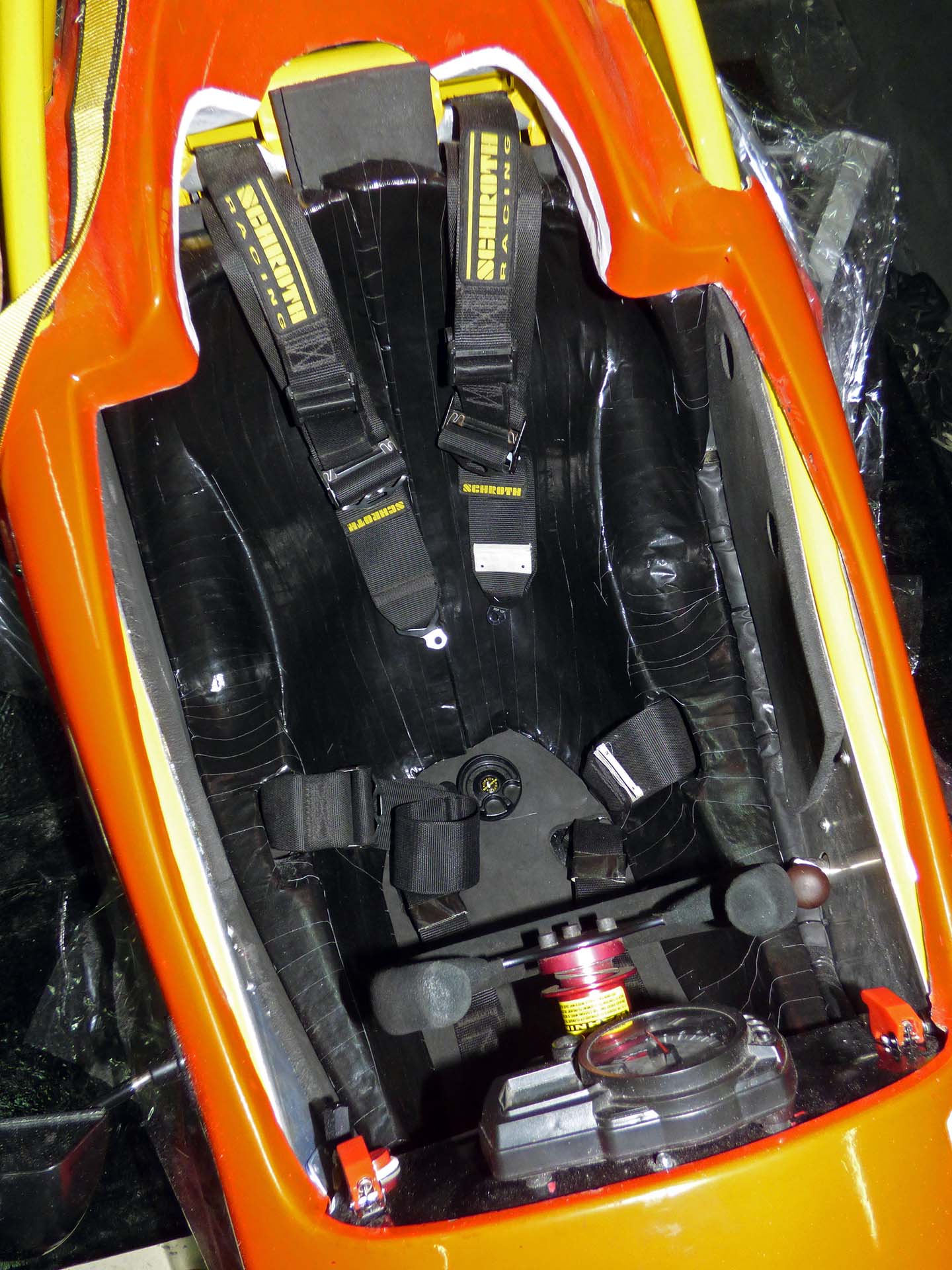
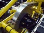
After I rested I went out again for several more laps trying to bring the speed up, doing a best lap around 1:28, still very slow for Bira. I brought the car in when my neck couldn’t take it anymore, after only about six laps. The issue was not so much cornering force as it was the wind pushing my helmet backwards; I just couldn’t hold my head up against it. We found a few issues like the torque spec on the left front wheel bearing was not high enough, leaving the axle free to wobble a bit in the bearing. Also, the left rear lug nut backed off, and the throttle cable came loose at the engine bracket. We increased the lug nut torque spec and reversed all the nuts so the flat side contacted the wheel as we decided the radius on the wheel was too small to properly contact the conical face of the nuts.

For the third run I brought the speed up more, with a best lap of about 1:21, but the car was undrivable at high speed. I believe it was actually bouncing in the air on the straight, as I could hear engine speed variations even when I wasn’t touching the clutch or gear lever. I kind of expected something like this as the springs are way too stiff. Anyway, the stiff springs bent the right rear suspension pushrod adjuster, and we were done for the day.

So overall, the suspension geometry feels perfect. The engine, transmission, electrical system, frame, steering, cooling and almost everything else worked flawlessly.

Wow, it fast! It’s the most amazing thing I’ve ever driven. It makes my old twin-plug 3.5 liter Porsche 930 feel like a tractor. But it demands precision and skill– I felt like an elephant learning to tap dance. As I’m sure you will see from the video, my shifting was all wrong. All the action in the clutch is in the first half inch, whereas the throttle pedal moves like four inches so coordinating the two was difficult. In addition, I was still driving it like a normal transmission, using the clutch on upshifts, as we decided to learn proper sequential shifting in a later test. I can see that with some suspension tuning, aerodynamics, tires, and a software upgrade for the nut that holds the steering wheel, the car will be seriously fast.

Thanks to everyone on Apexspeed who has provided advice, technical knowledge, and emotional support over the years. I couldn’t have done it without you!


Custom Molding the Seat

Finished Seat

Finished Seat

For the intermediate term I’ll be using a custom-molded seat insert made with readily available (and cheap) two-part urethane foam. I have a kit of the Indy/F1 style foam, but it’s so expensive I’m going to learn what I can from the cheaper seat first. I’ve learned useful things already: on the first pour the bag doubled over or stuck to itself and the foam didn’t make its way to the thigh area, so the first attempt was scrapped. It was also useful, however, in finding out where to slice the foam to get it out of the car easily, and learning how thin the foam will make itself under high pressure areas (zero thickness). So for the second attempt I first lined the entire cockpit with two layers of 10mm energy-absorbing foam before pouring the 2-part foam.

As it expands the foam pushes hard against any constriction, like your body. When it hardens it’s almost too tight to fit back into. Many hours of sanding and cutting are needed to make the fit reasonable and comfortable. As it is, I can’t even get into the seat with my wallet in my pants pocket. At first I couldn’t even breathe in fully with the shoulder harness straps moderately tight.

Building the Undertray / Floor

Finished Undertray

Finished undertray after painting rests in the mold for curing

Building the undertray started with building a surface large enough to hold it. It’s larger than it looks, so we had to laminate  decorative plastic laminate onto two 4×8 foot sheets of plywood that had been trimmed to about 3×8 feet each. Then wood to form the side air dams was screwed down, and the radii filled with auto body putty. Next we cut plastic honeycomb and plywood pieces to fit, with the plywood located to pick up the attachment points on the frame and to protect the radiators on either side of the car. I built a hot-wire foam cutter from a tree saw handle, a piece of guitar wire, and an automobile battery charger, which I used to cut foam profiles for the leading edge of the floor. Then we laid the whole thing up with epoxy and two layers of fiberglass on the bottom and one on the top, and vacuum bagged the whole shebang. Vacuum bagging was made more difficult by the random tiny holes in the plastic sheeting, which we expediently fixed by adding a whole second sheet on top of the first.

After debagging we painted it and found out the hard way that you can’t paint enamel over fresh epoxy in a humid climate. It never dried, and had to be scraped off like tar. Epoxy paint worked much better. We then mounted the undertray on the car, drilling mounting points through the plywood in the correct places. We had to fabricate a mount for the front of the undertray, which was a little tricky as we didn’t want to remove the fiberglass body panel under the driver’s legs so everything had to be done from the outside. We fabricated a small pylon from aluminum sheet and pop-riveted and epoxied it to the bottom of the body.

Laying Up a Carbon-Fiber Honeycomb Front Impact Attenuator

Impact attenuator

Nose in place while epoxying aluminum hard points into correct positions

SCCA FB rules require a metallic or composite front impact attenuator. Can’t have cars running around on the track with a battering ram on the front… My impact attenuation structure, or crash box, consists of a carbon-fiber and honeycomb sandwich laid up directly on the inside of the fiberglass nose. The carbon fiber varies from four layers at the front to eight layers around the rear attachment points so that it will crush progressively from the front to the back. Cylindrical aluminum inserts are used in the honeycomb as hard mounting points for the wing to the nose and for the nose to the chassis. This area is designed to be strong enough not just to absorb impacts but to allow lifting the front of the car by the front wing.

Carbon-Fiber Honeycomb Vacuum-Bagged Test Panel

Clicky Thingy

Click to watch the video on Youtube.

Inside the nose of the race car will be a carbon-fiber and honeycomb sandwich impact attenuator. So now’s the time to learn how to do vacuum bagging and sandwich layup. Also epoxy. So many new skills…

Fabricating the Chain Guard

Chain Guard

Finished chain guard in place

Formula 1000 rules require a chain guard equivalent to 1/4″ aluminum to contain the chain in case of a break. I had the blank laser cut, then bent it on my tubing bender. After bending, it was sliced in two parts for easier access to the chain and rear sprocket, drilled and tapped for an overlapping tab, cross-drilled for mounting holes, and installed.