Fabricating the Chain Guard

Chain Guard

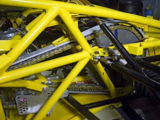
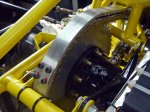
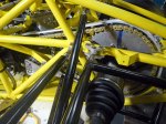
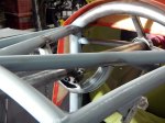
Finished chain guard in place

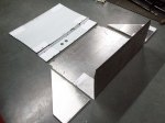
Formula 1000 rules require a chain guard equivalent to 1/4″ aluminum to contain the chain in case of a break. I had the blank laser cut, then bent it on my tubing bender. After bending, it was sliced in two parts for easier access to the chain and rear sprocket, drilled and tapped for an overlapping tab, cross-drilled for mounting holes, and installed.

Fabricating the Pedal Cluster

Voila!

Finished pedal cluster

Here’s a big project that spread out over a number of months. I’m aggregated the photos here and attempted to make them tell a coherent story.

The cluster as a whole can be adjusted forward and back for drivers of different heights. The gas pedal is adjustable for foot travel, throttle cable travel and left/right position. The brake pedal height is independently adjustable, and brake bias is adjustable from front to back. The hydraulic clutch pedal is also independently adjustable for height.

Many of the original pieces were laser cut from steel, then bent and welded to form the complex shapes required. Some of the bushings were CNC turned, but most were made by hand. The master cylinders, brake bias adjustment cable, and the nuts and bolts were purchased, with everything else custom made. This includes the brake bias adjustment assembly, which forced me to learn how to cut threads on the lathe. It’s not as easy as it looks. Take a look at the brake bias adjustment bar– it has three sets of threads independently cut on a manual lathe, three diameters, two snap rings and a threaded hole. Good fun! Due to changes in the steering rack mount, the main pedal bracket had to be widened as you can see in the photos.

Computer Rendering

Computer rendering from early 2011
Building the Firewall

Test Fit

Test fitting the firewall

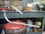
The firewall is a continuous, fully welded sheet of steel between the engine compartment and the cockpit. SCCA formula 1000 rules allow it to be a stressed panel, thus the continouous welding. Around the fuel tank it will be a double wall of steel for extra protection against engine explosions, insulated with shredded fiberglass to keep the fuel cool.

Fabricating the Fuel Tank

Fuel Tank

Finished fuel tank. You might want to wear sunglasses.

The fuel tank consists of an FIA FT3 certified fuel cell bladder, custom-made for this project by Aero Tec Laboratories, inside a custom made steel/aluminum container. The bottom and back of the container are made from a single laser-cut and bent sheet of steel, while the sides, front, and top are laser-cut and bent aluminum pieces. It’s carefully designed so the interior is completely smooth with all rivets and fasteners away from the fuel cell. All the rivet holes were laser cut also, meaning there’s only one way to fit it together– the correct way. This did make it very hard to install, however, as tolerances are zero to negative.

Inspecting or replacing the fuel cell bladder should be possible by drilling out all the rivets on the diagonal front panel and removing it. Not something I want to do very often.

Welding on More Random Jingly Bits

Shiny Frame

Some shiny frame porn for you…

I had not realized how many small brackets and things need to be fabricated and welded onto the frame before it can be painted. Weeks of work…

The nose mounts are so strong because the car will be lifted by a nose jack under the wing in the pits.


Mounting the Side Impact Panels

Side Panel

Aluminum side impact panels finished and mounted

SCCA Formula 1000 rules require side-impact protection consisting of either kevlar laminated to the inside of the body, or 0.060″ aluminum or 18-gauge steel bolted to the frame. To keep the side impact panels from being used as a stressed member, attachment points to the frame must be more than 6″ apart. Mine are laser cut from 1.6 mm aluminum. The mounting holes were also cut by the laser to be sure of the 6″ rule, but this was a mistake as it made the mounting tabs much harder to fabricate. It would have been much easier to weld the tabs in place with holes already drilled, then drill through the tabs to the aluminum panels for exactly aligned holes. As you can see from one of the photos below, the panels fit perfectly. This project was a lot of cutting and welding with little apparent progress.

Fabricating the Differential Mounts

Finished Diff

Finished differential, differential mounts, and rear sprocket

Thirty-four years ago I designed a car for the SAE collegiate Mini-Baja competition. The differential was inadequately supported in the middle, and although it didn’t break on us, it broke the next year and sidelined the car. I’ve felt guilty ever since, so that’s one mistake I’m determined not to repeat. This one should be adequate…

Later I plan on fabricating some sort of container or plugs to keep the oil in the diff.

Fabricating GSX-R1000 Engine Mounts

Sorry for the long delay since the last blog entry. A lot of water has gone under the bridge since then. But don’t worry, the project has continued, although with some big distractions. I’ll be trying to catch up on my blogging in the next few weeks.

Next up is fabricating the engine mounts for the 2007-8 Suzuki GSX-R1000 motorcycle engine. I surveyed the state of amateur formula-car engine mounts, and decided a lot of them are inadequate. This video got me to thinking: https://www.youtube.com/watch?v=m1j7hmJmSJA as my car should be faster than a Ferrari 458. Some might be skeptical of that speed comparison; if you are, take a look at this comparison of a Porsche 911 Turbo versus a formula 4 car: https://www.youtube.com/watch?v=e8WyvVbVu4k . A formula 1000 car should compare favorably with a formula 4 car. Either way, you lose a lot of torsional rigidity with the large open hole to mount the engine, and I hope to recover much of that with a strong triangulated set of engine mounts.


Fabricating the Steering Column

I originally sent all these parts out to the CNC shop, but they never got back to me with a quote so I ended up making everything myself. The spline onto the steering rack was a tight press fit, so for now the entire column including the rack is a single assembly. I don’t know it’s possible to remove the rack later, and I’m not going to try as it might destroy the rack. The U-joints are special units from Sweet Manufacturing in the US, but don’t seem to be anything special. In the future I might try to adapt standard Honda steering column U-joints and column splines. These use a perpendicular pinch bolt so the column can be disassembled at each joint.

Fabricating the Seat Bottom

Just a quick update here as the next one will be big and I want to keep it together as one post. I want to get all the tabs and brackets attached to the frame as soon as possible so I can paint it, so I started with an easy one: the seat bottom. I had the pieces laser cut, but the shop forgot that there are two identical side pieces and I had to cut that one by hand. I turned out to be easy after making a paper template. Each of the four pieces is a section of a cylinder and some of the edges intersect off-axis with frame tubes, so those lines that look straight really aren’t. The seat bottom is curved like this to get the driver as low as possible, mainly to keep the top of the main roll hoop as low as possible. The curvature was easy to make by just bending the steel by hand and fitting it by eye to the frame.

Attachment points are carefully spaced more than six inches from each other to comply with the F1000 rule outlawing stressed panels (with certain exceptions). It would have been much easier to just weld each piece to the frame tubes below it, but I don’t plan on this counting as the stressed belly pan. A stressed belly pan will be added to the planar bottom of the car. Making the seat bottom removable gives the advantage of easier access to the triangular compartment below it for mounting the fire extinguisher and whatever else will fit, and I can also replace the seat bottom later with a carbon fiber and kevlar version to save weight. At the moment I’m appreciating the fact that certain important body parts will be protected by two layers of steel in the event of a crash.