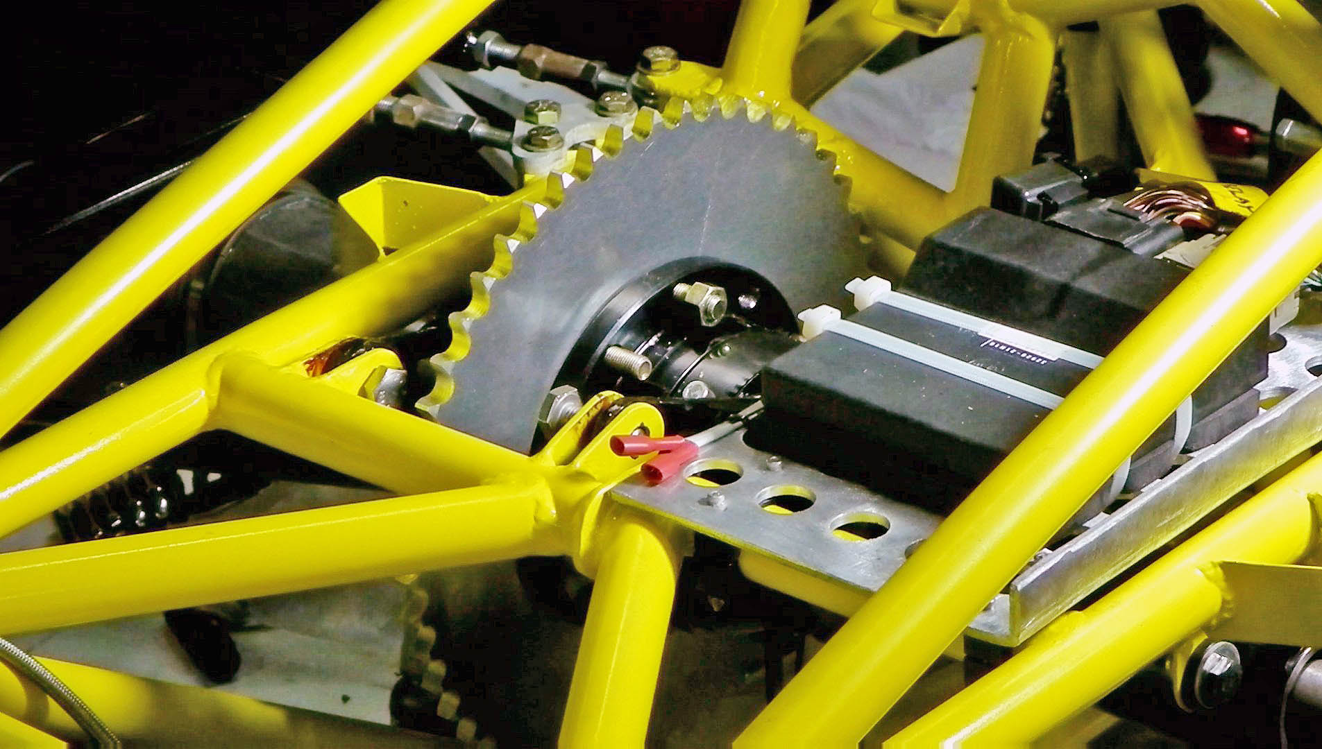
Rear Sprocket in place
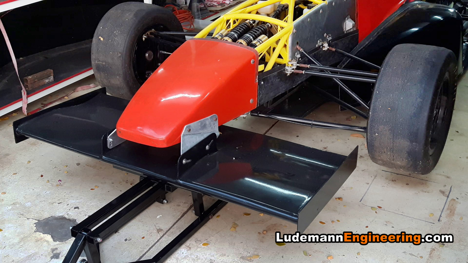
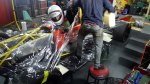
Completing the car is now just one long series of small projects. Three are shown here.
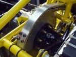
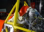
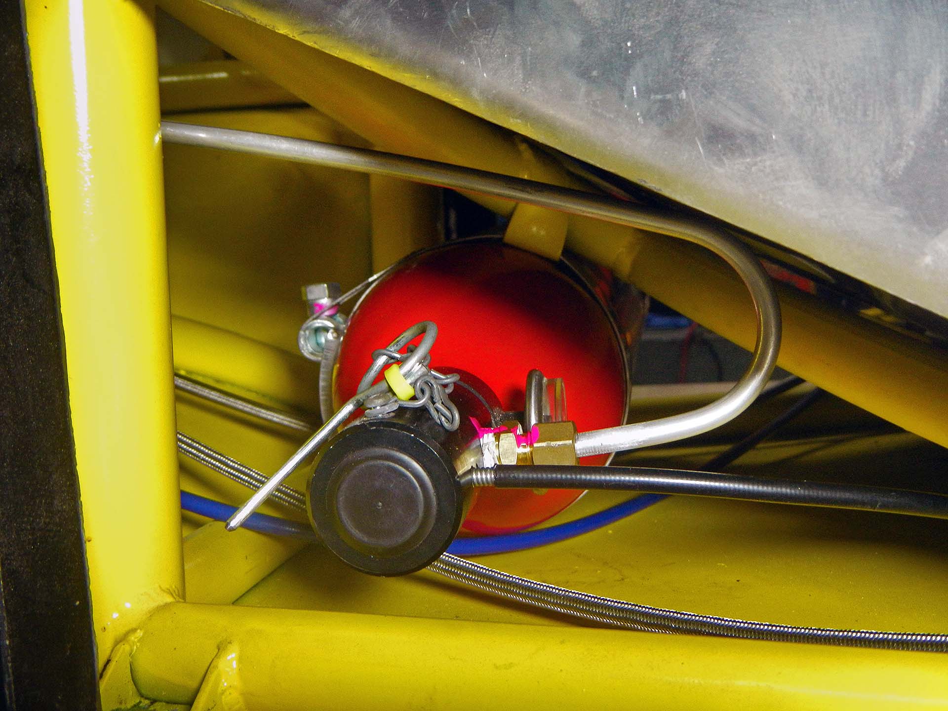
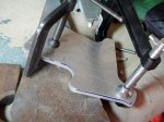
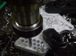
The original chain tensioner design was not able to take up enough slack in the chain. The chain was either too short or too long, no matter how many links I used or where I put the adjustment. I had to come up with a new design with two idler sprockets instead of one, as you can see in this post. The bearings are special ceramic hybrids to handle the extreme chain speeds seen with a GSX-R1000 engine.
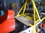
I’ve had a rear sprocket on the car for some time, but that was just for fitting. The lightening holes on that sprocket conflicted with the mounting holes required by the differential, so it wouldn’t have been strong enough. Instead, I ordered a blank sprocket from England and machined the correct mounting holes and center hole, then cut it in half on the bandsaw so that it could be mounted or changed without disassembling the whole rear axle and suspension.
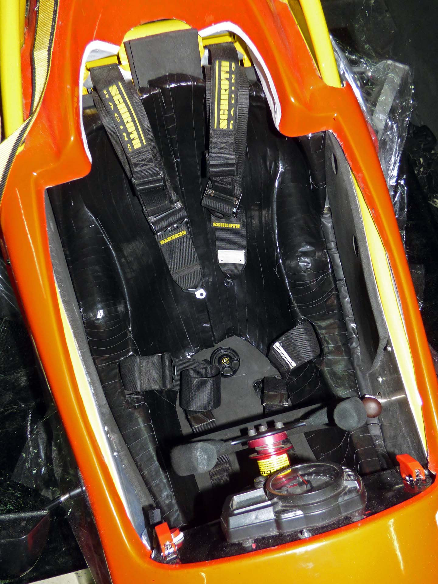
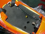
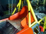
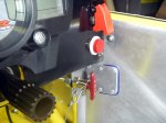
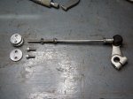
I also built an adapter to go from the auto shift linkage to the transmission gear change lever. I bought a Suzuki GSX-R shift link rod from Ebay, cut off the front, and welded it to a threaded rod. The rod threads into a bushing I made that fits inside the eye of the shift linkage. The sleeve of the shift cable must be held securely, so you can see here the bracket that mounts it to the frame rails.
-

-
Chain tensioner sprocket floats on shaft
-

-
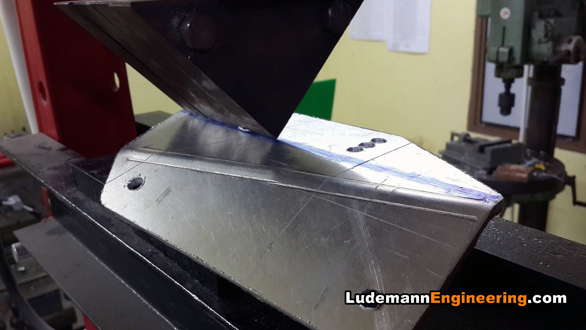
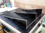
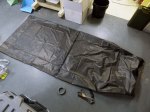
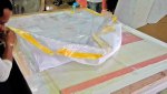
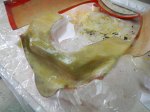
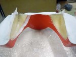
Starting the chain tensioner with a blank sheet of aluminum
-

-
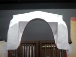
First side outline finished, scribed onto second blank
-
-
Grind the two sided to match with the angle grinder
-
-
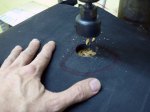
Drilling adjustment holes for idler sprocket shafts
-
-
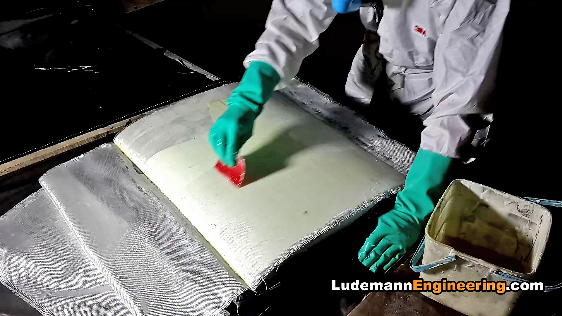
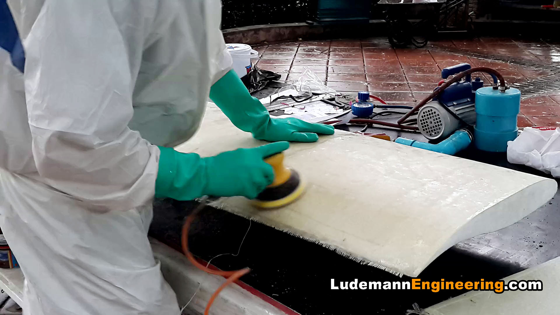
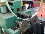
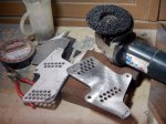
Polish them up with a Scotchbrite pad on an adjustable-speed angle grinder
-

-
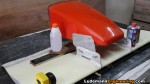
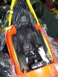
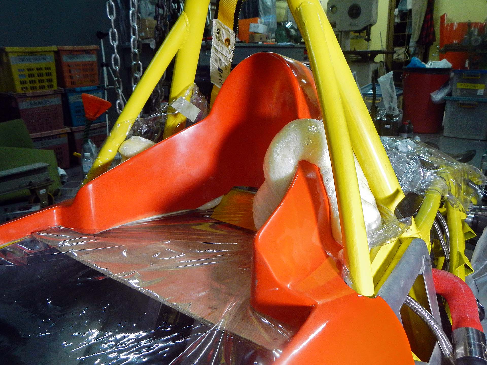
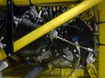
Chain tensioner in place, almost finished
-

-
Test-fitting new rear sprocket to old one as it can’t be mounted until cut in half.
-

-
Marking the rear sprocket for cutting, using the milling machine x feed
-

-
Milling the center hole in the rear sprocket on the milling machine rotary table
-
-
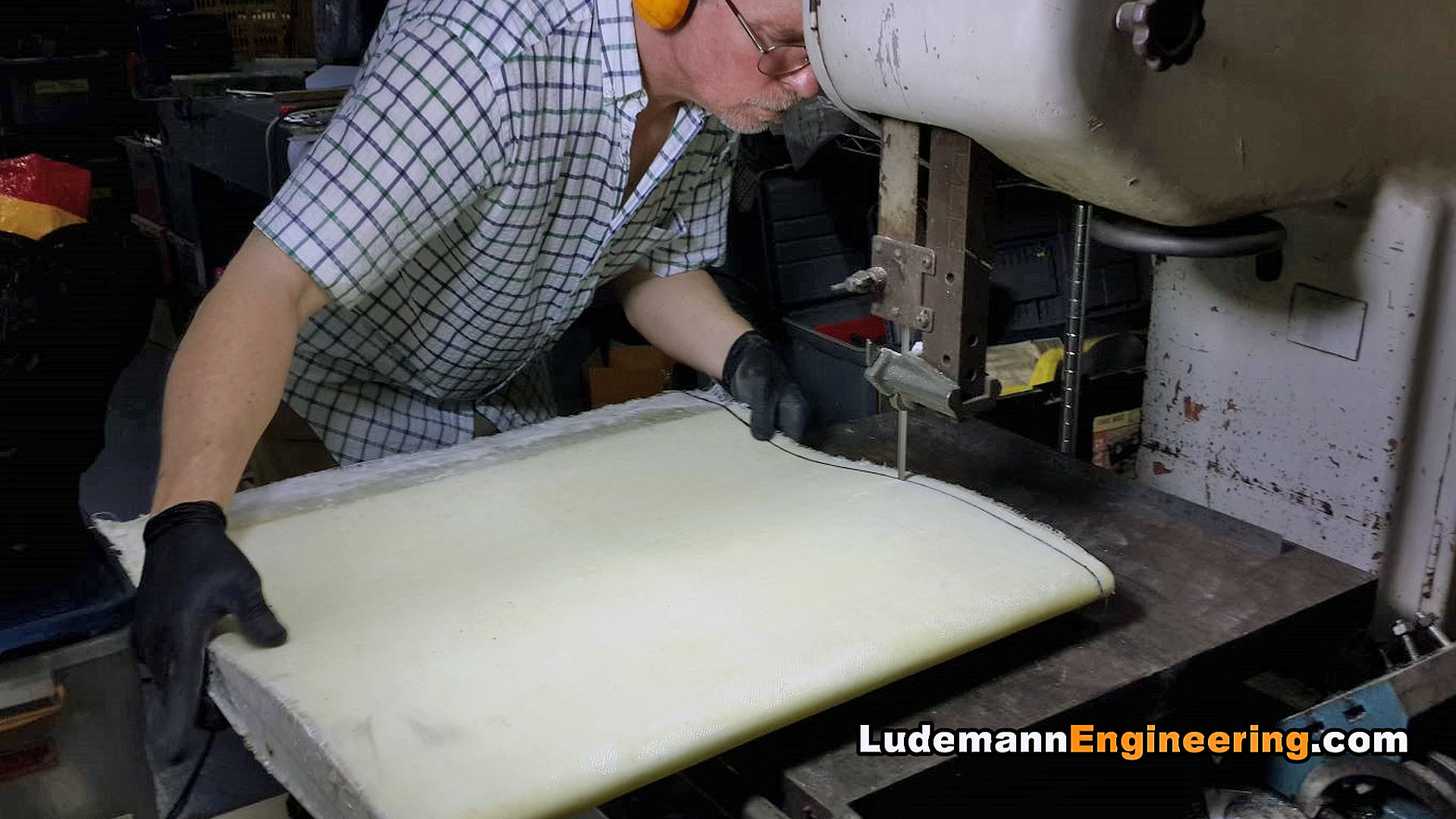
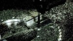
Cutting the rear sprocket in half on the bandsaw
-
-
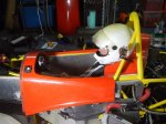
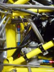
Adapter for auto shifter cable to GSX-R1000 transmission shifter shaft
-
-
Adapter in place, connected to gear selector shaft
-

-
Shift linkage rear mounting bracket