Completing the Chain Tensioner, Rear Sprocket & Shift Linkage

Rear Sprocket

Rear Sprocket in place

Completing the car is now just one long series of small projects. Three are shown here.

The original chain tensioner design was not able to take up enough slack in the chain. The chain was either too short or too long, no matter how many links I used or where I put the adjustment. I had to come up with a new design with two idler sprockets instead of one, as you can see in this post. The bearings are special ceramic hybrids to handle the extreme chain speeds seen with a GSX-R1000 engine.

I’ve had a rear sprocket on the car for some time, but that was just for fitting. The lightening holes on that sprocket conflicted with the mounting holes required by the differential, so it wouldn’t have been strong enough. Instead, I ordered a blank sprocket from England and machined the correct mounting holes and center hole, then cut it in half on the bandsaw so that it could be mounted or changed without disassembling the whole rear axle and suspension.

I also built an adapter to go from the auto shift linkage to the transmission gear change lever. I bought a Suzuki GSX-R shift link rod from Ebay, cut off the front, and welded it to a threaded rod. The rod threads into a bushing I made that fits inside the eye of the shift linkage. The sleeve of the shift cable must be held securely, so you can see here the bracket that mounts it to the frame rails.

Building the Axle Halfshaft Extensions


Rear Suspension

Rear suspension, axles and differential in place

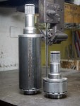
The car will use standard Honda Civic axle halfshafts, and I had the choice of cutting, sleeving and re-welding them, or building extenders that effectively widen the differential to meet the unmodified halfshafts. The cut/sleeve/re-weld option would eliminate the axle hardening and leave unknown strength, and I’ve since seen an example where this was done and the axle broke right at the weld. The option of “widening” the differential has several advantages. First, we can easily replace the halfshafts if necessary in the future with off-the-shelf parts. Second, moving the inner constant-velocity joint closer to the plane of the control-arm pickup points minimizes the plunge, or change in length, required as the suspension moves through its travel. Third, the halfshafts become equal length, eliminating torque steer. Now you may say “but, the extensions will be of different length and will twist unevenly so the torque steer won’t be eliminated”. The extensions will be much stiffer than the axle shafts so that won’t be the case.

So the choice was clear. We started with a differential and a couple of halfshafts as raw material…


Modifying the Wheel Hubs & Axles

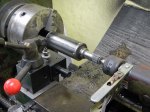
We’re using Honda Civic wheel hubs, wheel bearings, CV joints and axle halfshafts. They’re available everywhere, cheap, and light, and by using them we avoid having to cut matching pairs of splines. The wheel hubs are drilled for lightness and tapped to accept the wheel drive pins, then the two outermost pieces from two scrap CV joints are cut down to use as bearing retainers for the front wheels. Rear axle halfshafts are used in stock form, but extenders from the halfshafts to the differential will have to be fabricated later.

When cutting the CV joints I found that the contact faces are hardened some way into the joint, making cutting almost impossible (by which I mean “impossible”) beyond a certain point, even with carbide cutting tools. If they are heat-treated, maybe there’s some way to reverse the hardening? It’s probably something more exotic than that, though, as the hardening was highly location-specific.

Fabricating the Pushrods & Upper A-Arms / Wishbones / Control Arms

Finished

Finished set of control arms, tierods & pushrods

The upper control arms are all identical except that the bearing cups are mirrored from the left to the right so that the snap rings are on the bottom. If I can find a way to stake the spherical bearings then all four could be identical. Staking is a process that uses a hydraulic press to deform the bearing cup into a chamfer around the circumference of the spherical bearing, holding it permanently in place.

I printed out the layout of both control arms onto size A0 paper, glued the paper to a sheet of plywood, and drilled holes for the centerlines of each rod end and spherical bearing. This gives me a jig I can use for tack welding the parts in place. Washers under the bearing cups locate them vertically for tacking. The bearing cups proved a little too thin to weld without distortion, so I had to re-cut the spherical bearing bores after welding. Luckily I have an indexable end mill of just the right diameter, and running my mill at high speed with a lot of coolant gave a good finish on the bores. I then pressed the spherical bearings into place before painting as I wanted to make sure there were no glitches that would require messing up the paint to fix.

I sprayed Jotun Penguard 2-part epoxy paint directly onto the steel after first making sure the steel was scrupulously clean with a Scotchbrite pad on an angle grinder, followed by a cleaning with acetone and paper towels. The finish came out beautifully.

Building a Simple Hydraulic Press

I’ll be needing a press to insert the spherical bearings into the control arms and to insert the wheel bearings into the suspension uprights, so I took a couple of hours and built a simple hydraulic press. It’s just a strong steel frame that will give a small 5-ton hydraulic car jack something to push against. It’s taller than it is wide to be able to press items of different sizes by turning the frame on its’ side. Regarding painting, I’m finding that, with modern paints, I don’t need to use primer. I just clean the metal with a wire brush on a variable-speed angle grinder, clean it again with acetone and paper towels, then spray the topcoat on directly. This gives a thin, hard coat that sticks well.

Modifying the Lathe Quick-Change Toolpost

So I imported this quick-change tool post for my lathe, which appears to be some kind of standard, but a standard that my lathe just doesn’t happen to abide by. I needed a large (~1 1/2″) hole in the bottom of this solid tool-steel block. I tried drilling it with a carbide-insert drill, but after several minutes had made a cut so shallow it could only be felt by dragging a fingernail across it. After watching a few Youtube videos, though, I decided it must be possible and came up with the setup below, a solid carbide end mill slowly enlarging the hole on a rotary table. The mill left an amazingly high-quality finish.

Contents: 1 Race Car Kit, some assy. req’d

I’ve been accumulating parts for almost the past two years in a warehouse in Los Angeles as it’s easier to buy things in the US and ship them all the way to Thailand than it is to just buy them in Thailand. Also, I only wanted to navigate Thai customs one time. Finally gave them the go-ahead to ship, and a few weeks later everything arrived at my door. Includes just about everything that I can’t make myself or buy in Thailand: wheels, brake calipers, brake discs, brake pads, master cylinders, Aeroquip tubing and fittings, torsen differential, rear axles, spherical bearings, bearings, rod ends, 2007 Suzuki GSX-R1000 engine, crash padding, radiator, oil cooler, kevlar, vacuum-bagging materials, vacuum pump, Halon fire system, and more. Also, everything I need to fully fit out my machine shop, like a rotary table, angle table, and cutting tools. Better than Christmas!

Some assembly required. May require common household items such as tape, scissors, stapler, lathe, milling machine, and TIG welder.