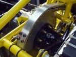
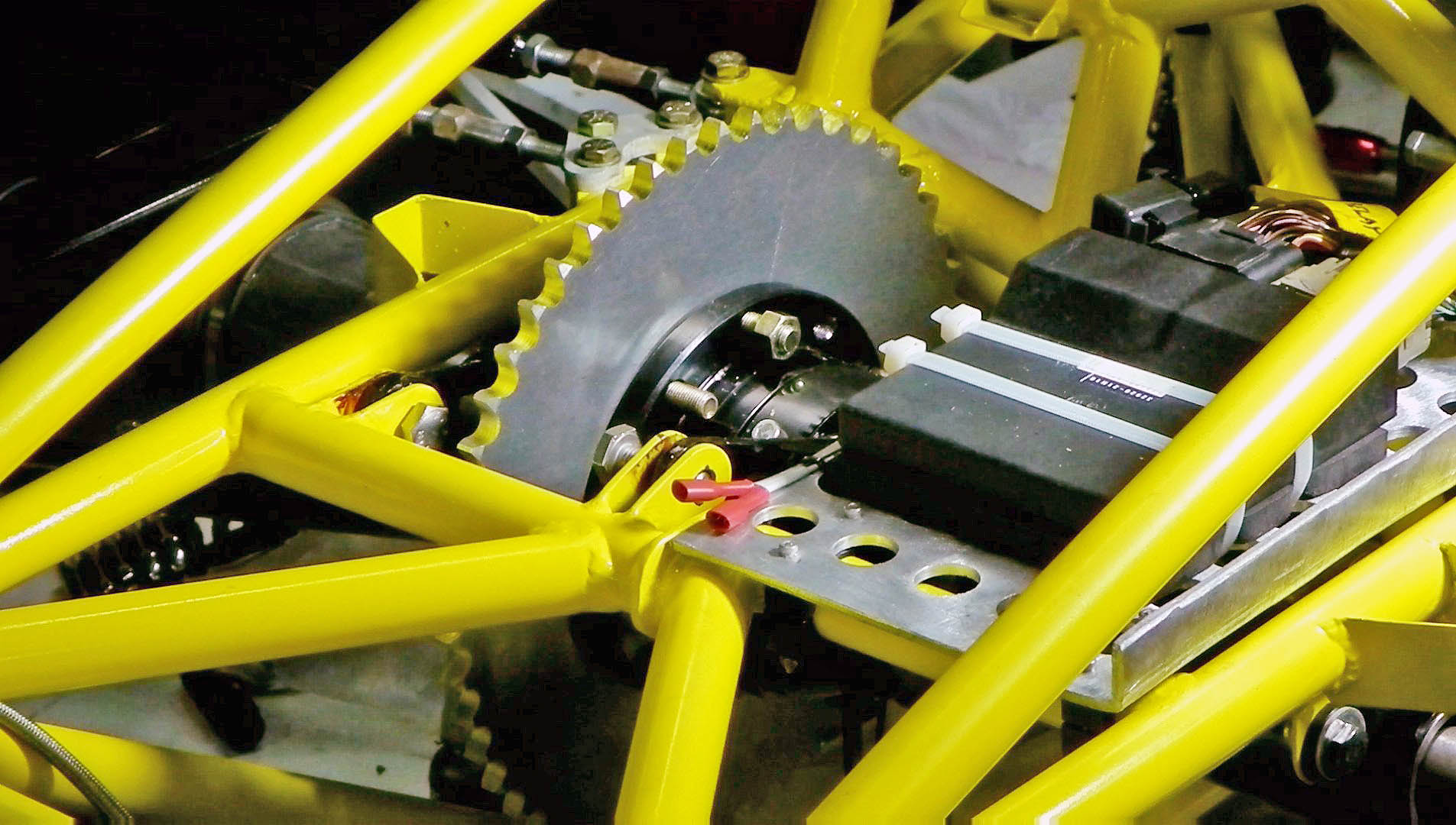
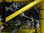
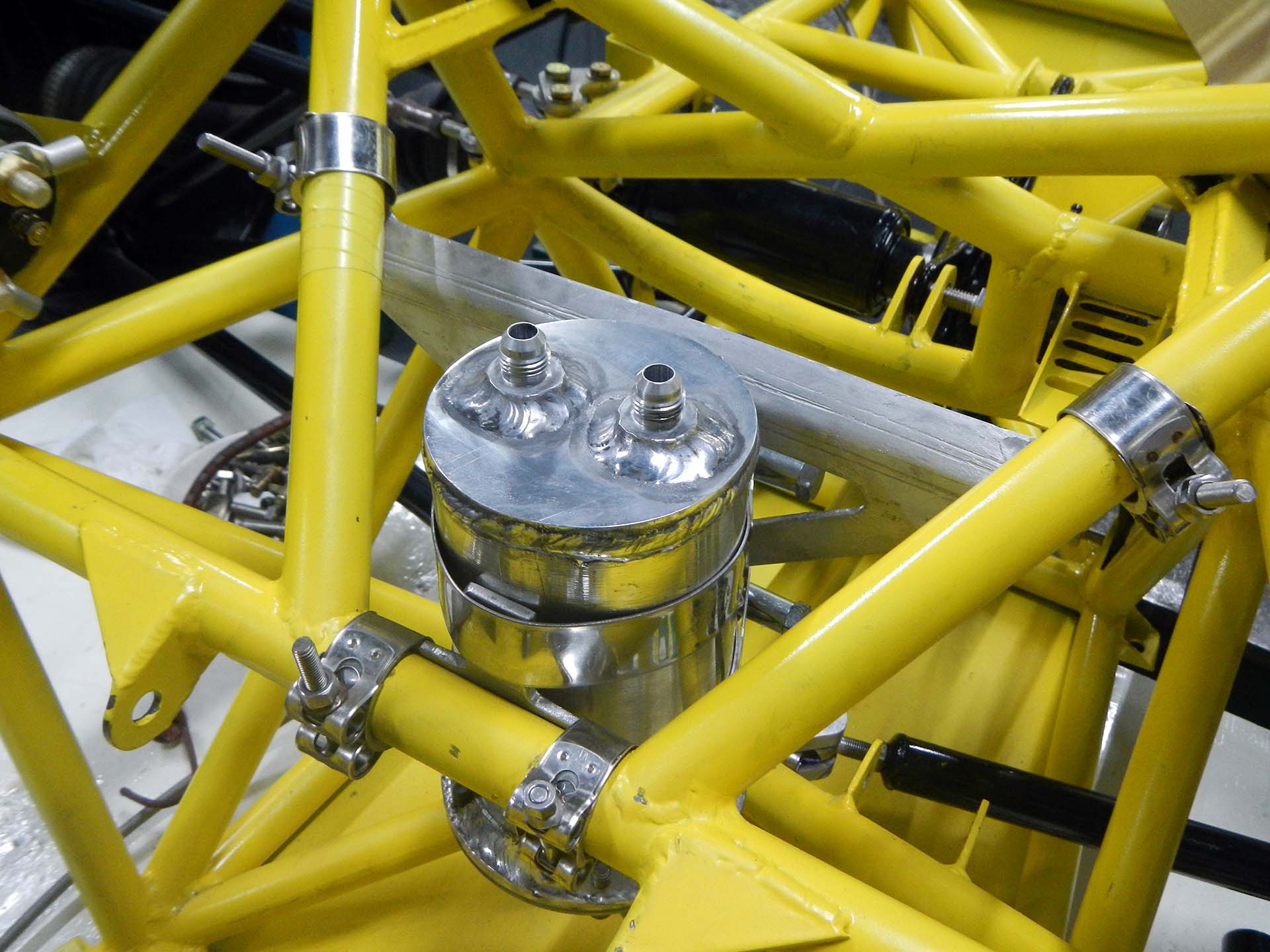
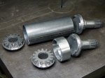
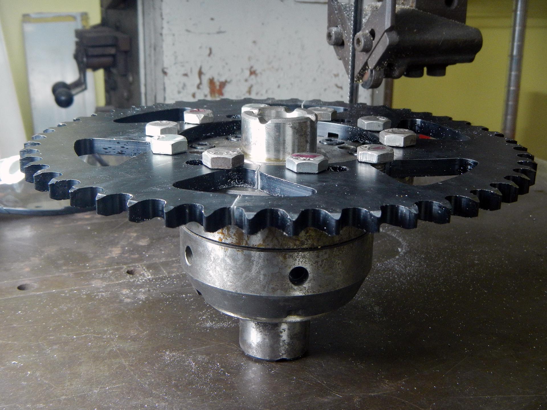
Rear sprocket mounted on the differential
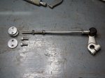
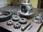
The limited-slip differential is a torsen or quaife type made by OBX, imported from the USA for an American-style Honda Civic. The differential ring gear on American Honda Civics is mounted with left-hand threaded bolts, so I blithely go down to the auto recycler here in Thailand and buy a differential for donor parts. Hmmmm… these bolts don’t fit. So I check carefully and find these differentials are sold in Thailand with right-hand threads! I go back to the auto recycler and ask for left-hand threaded bolts. They just look at me with that “crazy foreigner” look. OK, all we have to do is order some American-style bolts from Ebay US… There is exactly one listing on all of Ebay, and they don’t ship to Thailand! Plan B: drill the suckers out and use through-bolts.
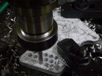
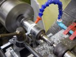
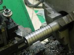
This is where I find out the differential housing is made of some ultra-hard tool steel, or maybe kryptonite or something. Wow, are these holes difficult to drill out. Solid carbide end mill, highest speed on the milling machine, lots of lubrication, and wait. And wait. And wait…
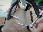
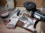
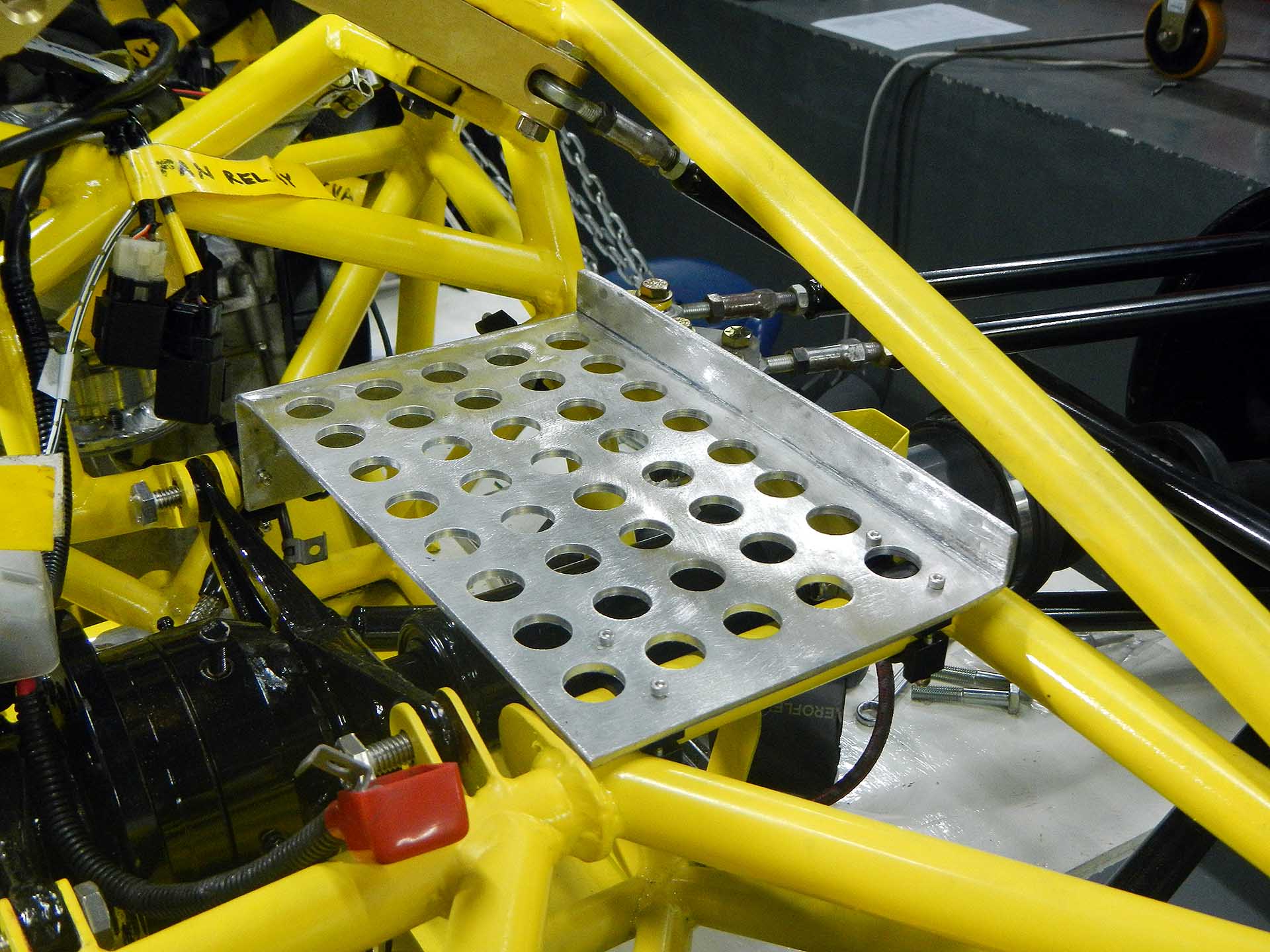
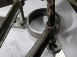
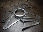
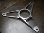
Next we had to drill a matching hole pattern in the rear sprocket, then cut it in two halves for quick changing at the track. This sprocket will be for static test only as the new hole pattern wasn’t compatible with the old one, leaving thin aluminum in some places. I’ve since ordered a blank rear sprocket from England which I will cut with only the correct holes.
-

-
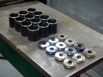
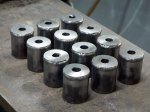
Drilling out the ring-gear mounting holes
-

-
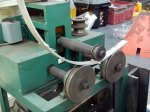
Drilling the diff mounting-hole pattern in the rear sprocket on the rotary table
-

-
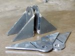
Cutting the rear sprocket in half for quick changes at the race track