Drawing: Overall Dimensions

Top Dimensions

Formula 1000 race car top view overall dimensions

I’ve been getting requests for the dimensions of the car from around the world. This should help. Some of the aerodynamic details have changed since this 3D model was made, so don’t take this drawing too literally. If you click on the image above you’ll get a PDF file with both top and side views dimensioned and in high resolution.

Designing and Fabricating the Steering Rack Mount

Rack Mount

Steering rack mount, ready to weld gussets.

Next step in getting the car rolling is to mount the steering rack. These parts were not laser cut but were cut with angle grinders and my bandsaw, because they’re, um, a design improvement. Yeah, a design improvement, that’ll work. It took me months to find a blade for my bandsaw, because Thailand. Anyway, now it’s useful for these kinds of tasks.

Once again we have something that looks simple, but took a great deal of thinking to arrive at. As Steve Jobs said, “Simple can be harder than complex: You have to work hard to get your thinking clean to make it simple.” I used to do almost exactly what Steve Jobs did; in fact, he once called my boss to persuade him to cancel the design we were working on, because Jobs was going to do it better (he didn’t). So I understand precisely what Jobs meant about simplicity. That might help explain why this was my fifth complete design for this subassembly. One downside of mechanical design: when you’ve sweated out an elegant design, anybody can take a casual glance at it and say “OBviously”. To which I reply, “OK, there’s probably an even better design out there somewhere. Let’s see you find it.”

Also attached are a few of the finite element analysis (FEA) tests that I performed to verify and improve this design.

Shiny Happy CNC Parts

I’m getting some interest in the car from here in Thailand, but they want it SOON. So I’ve had to step up the rate of progress, even though it hasn’t showed here on the blog. Instead, I’ve been designing and designing and designing… It’s a big step from an assembly design that seems pretty much correct, to a set of drawings and IGES or DXF files that you’re willing to pay real money to fabricate. Everything has to be checked, from the load cases used in the finite element analysis to the hole clearances for every bolt.

For example, did you know that a 1/4″ bolt doesn’t go into a 1/4″ hole? The proper size of the hole is 0.257″ for a close fit or 0.266″ for a free fit. Of course, then you have to take into account the width, or kerf, of the laser beam used to cut the metal, which can be 0.01″ or 0.25mm but varies with the type of material and thickness being cut, and the laser beam is actually a cone that can be focused on the top, middle, or bottom surface of the piece. Many parts had to be redesigned for the materials and processes I’ve been able to locate in Thailand. Here it’s not a simple matter of looking up all the local suppliers on Google and giving one a call. Thailand has a great number of very small companies that rarely have websites, and even if they exist they’re mostly in Thai, which as a special favor to web search engines uses no spaces between words. Yes, you read that right. Using no spaces would be OK if there were only one way to parse a stream of Thai characters, but haha, you make joke, eh? And then if I can actually get someone on the phone, I have to communicate in Thai. Like that’ll work.

Last year I was looking for a foundry to cast aluminum uprights, and I found one (using Startpage, not Google) less than an hour from here. Their website had a Google map and everything! So I drive there, and I’m within 100 feet or so, asking motorcycle taxi drivers where the company is. No idea; there’s never been a foundry around there. I show them the address and they say oh, that’s way over on the other side of town. The person answering the phone number has no idea what I’m talking about. I give up.

On the other hand, recently one of those Google ads that look like the first links on your search actually showed me something that I needed and couldn’t find with a search: a small local company that fabricates custom radiators. So I managed to find their shop this week and got a quote for the radiator. Quote comes by email entirely in Thai. Google translate does a pitiful job of translating Thai, but I caught on the email wasn’t spam. Fantastic price, by the way. Cheaper than what I paid for a used race car radiator on EBay. I decided I didn’t really like how that one would fit, so I designed one that’s ideal for my application and figured I’d worry about fabrication later. Problem solved, yay!

The Thai racers who are interested in the project have emphasized that the price is crucial, which means more redesign. Surprisingly for me, this is the same thing I’ve heard from the people in Singapore who’ve contacted me. Sometimes it’s easy to dash off a quick machined aluminum design, but it takes a lot more thinking to do it with laser-cut steel pieces. The equivalent in steel typically ends up being a little heavier, but that’s an example of why Formula 1000 has a minimum weight rule. Laser-cut steel hand-welded into a complex component is just about free in Thailand.

Where before I was planning on making just about everything in my machine shop, now I’m looking at fabricating as much as possible at subcontractors. Luckily a friend found a large CNC machine shop not too far from here, and the guy running it speaks English and understands drawings and computer files and tolerances and clearances and everything. I’ve now received my first batch of CNC machined parts from them and they look great. Combined with the first batch of laser-cut parts and a few parts I’ll fabricate and modify myself, I now have everything to make the car a roller.

Anyway, on to today’s gallery:

Building the Body Buck: Part 1, Ribs & Foam

Here’s what we’re building, sort of. Rather than build a CAD model of an actual assembly of stringer and rib parts, I extruded cuts into the solid model so that the slots will appear in the correct places when I make cross-section drawings at the appropriate locations. This is actually harder to visualize than you might think. I wasn’t sure it would go together flawlessly, especially since the cuts in both the ribs and stringers went to two different depths depending on the typical height of each region. I didn’t want long floppy sticking up from the cuts:

Body Buck CAD

Original 3D CAD model showing slots for assembling plywood ribs and stringers.

Hot Off the (3D) Press: Suspension Upright 3-D Print

The suspension uprights have gone through a long evolution, but I’m zeroing in on the goal.

First Design: Machined Billet Aluminum

This design uses radial-style brake caliper mounting. Needed to be redesigned when someone ordered the lug-mount calipers and had them delivered all the way from the USA. Probably a Freudian slip as they’re less expensive.

Machined Upright

Second Design: Fabricated Steel

Fabricated Upright

Second design was fabricated from steel. Unfortunately, welding will eliminate the temper in the heat-affected zones. The weakening due to this is hard to predict, and can only be eliminated by heat treatment. That would mean days or weeks finding and learning to deal with a heat-treatment supplier.

Mesh Quality

Mesh used for finite-element analysis of fabricated steel upright.

Upright FEA

Finite-element analysis stress plot for fabricated upright. Strong enough, but where are those heat-affected zones?


Third Design: Cast Aluminum

Here’s the final result of literally hundreds of design revisions, ensuring that the upright is strong enough and as light as possible. This design is made possible by the new technology of 3d printing, which will be used to make the master “plug”, from which molds will be made to cast the actual part. Note that the steering arm is not an integral part of the upright, but is modeled together with the upright because the FEA runs much faster this way.

FEA mesh plot for cast upright

FEA stress plot inner

Cast Upright FEA

View from outside

Finally, the Master Copy

The upright had to be split into four pieces for 3D printing; split vertically so I can make two mold halves and remove the masters from the molds, and split horizontally to fit the 3D printer. The 3D printer extrudes hot ABS plastic in X-Y layers onto a heated Z-axis stage with 0.3mm resolution. The print is slightly rough and the parting plane is slightly warped, which will have to be corrected with auto body putty, primer, sanding, and paint. The cast aluminum blank will still require several machining steps to cut off the gate and sprue, drill mounting holes, bore the bearing hole and retaining ring slot, and mill the brake caliper mounts. Still far better than trying to machine individual parts (or even a mold pattern) this complex, which would be approximately impossible and semi-infinitely expensive.

Beautiful, huh?

One half printed in two colors to highlight the split required to fit it into the 3d printer

Set of 4

Full set of four 3d prints. The cylinder protruding in the upper left is the gate, where molten aluminum will be poured into the finished mold.

Top View

Some people get excited by shoe sales. I get excited by this!


Redesigning Suspension Components

So I was ready to build the suspension attachment points and decided I’d better do a finite -element analysis. It turns out they needed a lot of tweaking, and in a shin-bone’s-connected-to-the-thigh-bone kind of way, I ended up redesigning just about every suspension part all the way to the lug nuts. Part of this came when the quote on building the upper suspension attachment clevises came in way higher than expected, so I redesigned them so they could be laser-cut, hopefully much cheaper than CNC machining. Don’t have the new quote yet.

Also, I received the huge shipment of parts, supplies, and tools that I’ve been aggregating in LA for almost the past two years, and some idiot in purchasing (me) managed to order the wrong brake calipers. Everything was right except for the mounts, which are the lug style instead of the radial style. At least now I really know the tradeoffs between the two approaches. The upright for lug mount brake calipers is only about 35 grams heavier than the one for radials, and the calipers are $80 cheaper each. Over $1000/pound for that weight savings… Actually, that’s not quite fair as I don’t know the relative weights of the two caliper styles.

Anyway, we have lots of pictures of FEA meshes and results:

How to Fishmouth Tubes in Solidworks

After playing around with various kinds of hole cutters, mills, angle vises, and so on, I’ve settled on the best method for cutting fishmouths in tube ends so they fit together properly when building a tube frame with round tubing. Since the tubes will be welded they don’t have to be perfect as you would get by using a milling machine. Also, the typical joint has several tubes meeting which need to accomodate each other, and on a milling machine this would take a separate setup for each tube at each joint, taking an inordinate amount of time. Forcing Solidworks to show the correct shape of the ends of each tube requires some real work, an explanation of which I found over on the LoCost website. I’m going to provide a modified and updated tutorial here.

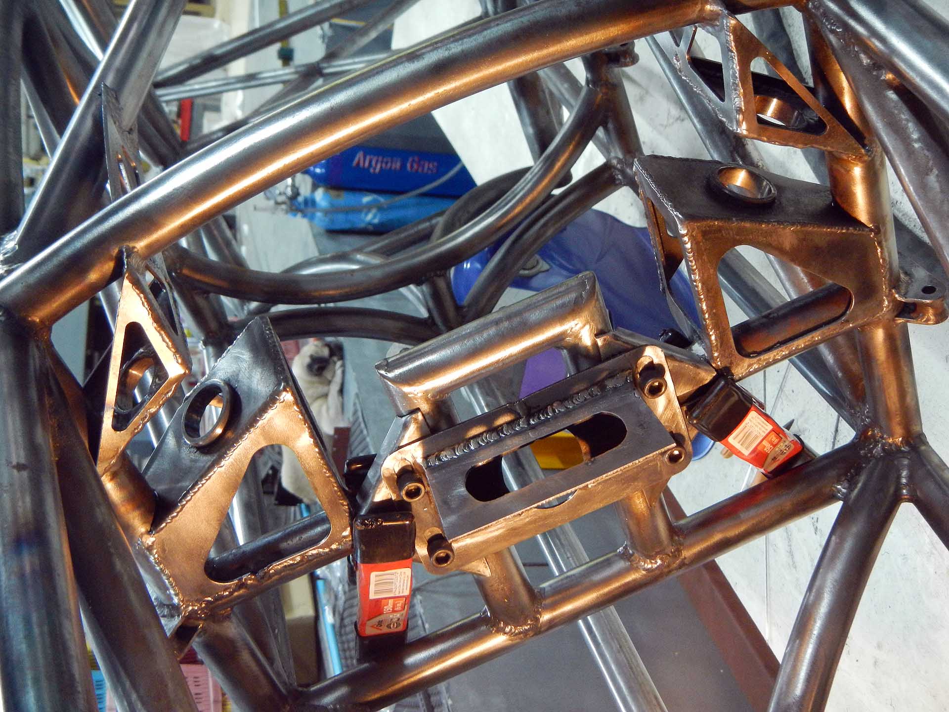
The first thing to understand is that each tube must be fully welded before adding the next tube. This makes the finished structure much stronger than if you tacked all the tubes in place and simply welded around the remaining visible joints. Here’s an example:

Welded Joint

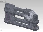
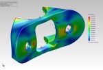
In a multi-tube intersection, the first two tubes are fully welded before adding the next tube

Third Tube

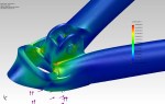
Third tube in place before welding

Third Tube Welded

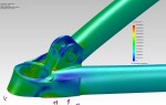
Third tube fully welded

Solidworks Tutorial

Although the following tutorial may look long and complicated, once you understand what’s going on each step will only take seconds. And believe me, it’s much faster than grinding a tube to fit using trial and error. More accurate, too.

Weldment Profile

First, create a weldment profile with the correct outside diameter, a thickness of 0.1mm, and a gap of 0.1mm as shown.

Original Weldment

Original weldment use a profile of 25.4 x 1.0 mm round tube

Replace Profile

Replace this with the new, slitted profile

Check Trim

Each tube will need to be trimmed to the tubes around it, reflecting the order in which they will be assembled. Insert > Weldment > Trim/Extend. Check your trims.

New Part

Select the tube, right click and choose "Insert into new part".

Save Part

Save the part with a descriptive name. I keep a separate directory of tubes.

Sheet Metal Bends

Select an INSIDE EDGE and click Insert>Sheet Metal>Bends.

Click OK

Just click the green check mark. No need to fiddle with any options.

Suppress Bends

Right click on "Process Bends" and choose "Suppress".

Flattened Tube

And you get a flat sheet.

Get Normal View

Select he surface and choose a normal view

Normal View

With a Normal View, dimensions and shapes will be correct.

New Drawing

Open a new drawing and insert the current model view.

1:1 Scale

Set drawing scale to 1:1, full scale

Rotate View

Right click on the drawing view and choose Drawing Views > Rotate View.

Rotate View

Through trial and error, figure out how much to rotate the view so that it is horizontal.

Now Horizontal

Now we have a horizontal drawing view.

Insert Another

Insert another drawing view...

Current View

Also of the current model view.

Rotate Again

Rotate the view as before to get another horizontal view.

Two views

Two views on one drawing.

Align Horizontally

Align the views horizontally by right clicking on one view and choosing Drawing Views > Align Horizontally by Origin.

Draw Rectangle

Crop each view by first drawing a rectangle with 4 lines. The automatic draw rectangle won't work because it uses the unrotated axes.

Crop View

Crop the view by selecting the four lines of the rectangle, right click and choose Drawing Views > Crop View

Shortened Tube

Now we have both tube ends with the middle removed, fitting on a single A4 sheet.

New Sketch

Now we need a reference for how far the ends of the tube are from each other. Go back to the tube part and create a sketch like this.

Extrude Cut

Using the sketch, extrude a cut through the part and keep all bodies.

Cut Part

The part now looks like this.

Drawing Annotations

Go back to the drawing and add annotations as necessary for use in the shop.

Save as PDF

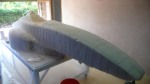
Save the file as a PDF and print it out on sticker paper. Cut out the 2 ends and stick them on the tube at the indicated distance. Use an angle grinder to grind to the lines.

Calculating the Loads on the Front Suspension

Suspension FEA

Simplified left front suspension finite element analysis result

It’s time to finalize my parts order, which means I have to pick all the rod ends and spherical bearings for the suspension. Up to now I’ve relied on rules of thumb, which isn’t good enough for a state-of-the-art race car. So I simply opened up one of my higher-level chassis models in Solidworks, one with most of the suspension attached, and created a 3D sketch of the upper and lower left front suspension A-arms, constraining the endpoints of the lines to the centers of the rod ends and spherical bearings. Then another line to simulate the upright and tire, and I’m done with the sketch. Then I created a structural member along each line and opened a static simulation study. In the study I constrained the inboard ends of the A-arms to zero translation and applied a 1400 pound load toward the rear of the car to simulate 4-G braking. Run the study, and voila! axial loads on each member.

Upper Front: 785 pounds

Upper Rear: 1211 pounds

Lower Front: 2639 pounds

Lower Rear: 3096 pounds

This allows me settle on 1/4″ rod ends for the inner upper attachments, 3/8″ for the inner lowers, a 7/16″ spherical bearing for the upper ball joint, and a 5/8″ one for the lower ball joint. All chrome moly alloy. Even these are far stronger than indicated necessary by this analysis, but I don’t want to deviate too far from standard practice on this design. Maybe transitory loads can be far higher?

Calculating the Loads, Round II

At the urging of a poster on ApexSpeed.com who insisted my calculations were inaccurate due to the non-zero joint stiffnesses, I re-ran the analysis with the suspension a-arms modeled as trusses. A truss model allows only axial loads on a member, using hinges at both ends to zero the moments. This gave me results that were the same +/- 2%, which makes no difference given the uncertainty in estimating the operating loads.

However, I also refined my model to include the suspension pushrod and that did indeed give me a different result. With the pushrod in place I could model the vertical load due to the weight of the car and the aerodynamic downforce. I’m now working with a braking force of 1600 pounds and a vertical load of 1230 pounds, which assumes a coefficient of friction of 1.3 for the tire on the surface of the track. This gives me the following axial forces:

Suspension

Left front suspension modeled as a truss with pushrod

Upper Front: 1103 pounds

Upper Rear: 1258

Lower Front: 4432

Lower Rear: 2366

Pushrod: 2357

Note that including the vertical load and increasing the braking load shifted the most highly-loaded member from the lower rear to the lower front, and increased the maximum load from 3096 to 4432 pounds, or 43%. The chrome-moly 3/8″ rod ends I’ve specified for the lower a-arm inboard joints still have a safety factor of 2.14 under these conditions. The posters on ApexSpeed have strongly warned me against using 1/4″ rod ends in the suspension, so existing inventory will be used in a different application and the upper rod ends will be upgraded to 8mm. It appears that only metric rod ends are available locally. Under these assumptions the pushrod rod ends will have to be further upgraded to 10mm, although I hate to have a whole separate part for just the pushrods, so I’ll have to re-examine the assumptions.

Designing the Chassis Jigs

Frame on Jig

Chassis in place on chassis table with all jigs in place

I had been trying to keep the chassis jigs in my head, but finally decided they’d probably come out better if I put them on paper first. So I spent the past few days designing them, and it became quite clear why I couldn’t keep them all in my head. I intend to bend the top chassis rails in one continuous curve as that will add a lot of style to the chassis. A lot of race car frames look like industrial equipment, but I have something in mind more like an Ariel Atom exoskeleton car, where the frame is so beautiful you don’t even need a body. Of course the car will have a body for aerodynamic, esthetic, and safety reasons, but I’d like people to see the frame without the body and still say “Wow!”. Now, the top rails are splines, not just arcs, and the only way to really bend one properly is to know where it’s supposed to be in 3-d space along it’s length, and that’s where the chassis jig comes in. When the chassis jigs are all in place, it will give me target locations all along the length of the frame that I can bend the rail to fit.

I eventually ended up with 22 pages of drawings that look like this:

Sample Jig

1 of 22 chassis jig drawings


And two pages of drawings that look like this:

Cross Rails

Sample chassis jig cross rail drawing

Free Download: Swing Set Drawing

Swing Set Drawings

Free Download! Children's playground swing and slide set

Just for grins, here are the plans for the children’s swing set and slide in case anyone wants to build one him/herself. Note that I specified the tubing thickness at 1.6 mm, where I built mine with 1.2mm tubing. I felt that it could benefit from being stiffened up a little more. Also not shown on the drawing is the attachment points for the swings and a set of chains up one side of the main structure that form a ladder. I’ll post a photo of the finished project later for reference.