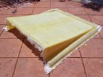
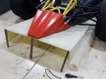
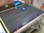
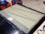
Building the Front Wing & Mounts

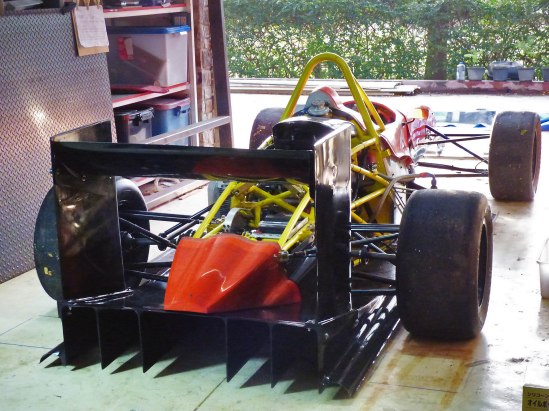
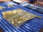
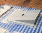
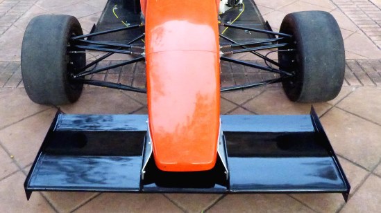
Front Wing

Finished front wing on the car (endplates to be added after setting ride height)

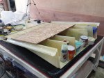
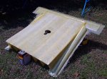
Fabricating a Formula 1000 Race Car Diffuser

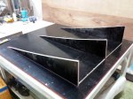
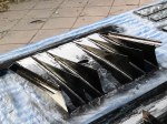
Diffuser

Finished diffuser mounted on car

I try to post updates only for completed projects, and since I’ve had several projects in progress it’s been a while since I’ve blogged. The diffuser is finally finished, so here are some pix and a video that explains it all:


Painting the Frame

Painted Frame

Painted frame, back in the lab

As you’ve probably figured out from looking at some of the photos below, I’ve painted the frame. I used Jotun Penguard 2-part epoxy right over bare metal after cleaning the metal with wire brushes and acetone. It took a few days as I had to let it cure before turning it, and all four sides had to be painted in turn in order to get every spot. No magic here, just lots of elbow grease.

Fabricating the Pedal Cluster

Voila!

Finished pedal cluster

Here’s a big project that spread out over a number of months. I’m aggregated the photos here and attempted to make them tell a coherent story.

The cluster as a whole can be adjusted forward and back for drivers of different heights. The gas pedal is adjustable for foot travel, throttle cable travel and left/right position. The brake pedal height is independently adjustable, and brake bias is adjustable from front to back. The hydraulic clutch pedal is also independently adjustable for height.

Many of the original pieces were laser cut from steel, then bent and welded to form the complex shapes required. Some of the bushings were CNC turned, but most were made by hand. The master cylinders, brake bias adjustment cable, and the nuts and bolts were purchased, with everything else custom made. This includes the brake bias adjustment assembly, which forced me to learn how to cut threads on the lathe. It’s not as easy as it looks. Take a look at the brake bias adjustment bar– it has three sets of threads independently cut on a manual lathe, three diameters, two snap rings and a threaded hole. Good fun! Due to changes in the steering rack mount, the main pedal bracket had to be widened as you can see in the photos.

Computer Rendering

Computer rendering from early 2011

Fabricating the Pushrods & Upper A-Arms / Wishbones / Control Arms

Finished

Finished set of control arms, tierods & pushrods

The upper control arms are all identical except that the bearing cups are mirrored from the left to the right so that the snap rings are on the bottom. If I can find a way to stake the spherical bearings then all four could be identical. Staking is a process that uses a hydraulic press to deform the bearing cup into a chamfer around the circumference of the spherical bearing, holding it permanently in place.

I printed out the layout of both control arms onto size A0 paper, glued the paper to a sheet of plywood, and drilled holes for the centerlines of each rod end and spherical bearing. This gives me a jig I can use for tack welding the parts in place. Washers under the bearing cups locate them vertically for tacking. The bearing cups proved a little too thin to weld without distortion, so I had to re-cut the spherical bearing bores after welding. Luckily I have an indexable end mill of just the right diameter, and running my mill at high speed with a lot of coolant gave a good finish on the bores. I then pressed the spherical bearings into place before painting as I wanted to make sure there were no glitches that would require messing up the paint to fix.

I sprayed Jotun Penguard 2-part epoxy paint directly onto the steel after first making sure the steel was scrupulously clean with a Scotchbrite pad on an angle grinder, followed by a cleaning with acetone and paper towels. The finish came out beautifully.

Finishing the Body Master Pattern

I ended up applying ten coats of SikaFloor epoxy to try to build a hard base for further finishing. Even this gave me problems, though, as it appears that the two-part urethane foam continues to expand indefinitely. Every time I would finish a section, next time I looked at it, it needed more work. For a long time I just thought my eyes were getting more demanding, but I finally realized the body buck was slowly changing shape, bulging out between the ribs. Once I figured this out, I just tried to finish the molds as fast as possible. I also installed air conditioning in this part of the workshop, and kept it running at night to avoid temperature-cycling the pattern.

If you’re thinking of doing this yourself, a better way to do it would be to just fiberglass straight over the plywood forms, using tape or something to support the first layer of fiberglass while curing. About a 3mm fiberglass shell should do it. Then use body putty right over that, using standard auto-body finishing techniques. That way there’s no foam between the ribs to push outward and mess up the shape. The only time you need foam is when you’re really sculpting something, like the sidepod air intakes. Oh, by the way, plan on about 1,000 hours of work.

After the floor epoxy there were several rounds of primering, puttying and sanding, followed by two coats of black two-part epoxy paint. This was sanded with 400, 800, 1200, and 2000 grit wet-or-dry sandpaper, then machine-polished with rubbing compound. The top layer was 9 coats of “Hi Temp Mold Release”, applied by hand strictly according to the instructions.

When I started to think about how to split up the body panels, I realized that the “horse collar” head surround would be impossible to remove when the car was finished, as it would interfere with the main roll hoop. This necessitated going all the way back to the SCCA rule book, where I took another look at the minimum cockpit opening specifications. I found that I could meet the minimum cockpit opening size with a fixed head surround, but I had to cut the “arms” off it. So, you get to see that surgery in the photos below.

Building the Body Buck: Part 2, Putty, Prime, Repeat

Sikafloor

After the first coat of ultra-hard Sikafloor epoxy

Here’s where the heavy lifting begins. Many, many passes of plaster or putty, sanding, and primer. The first step was to coat the entire body in plaster, which is best done the messy way: just plunge your hand into the bucket of plaster and smear it on the body buck. Plaster is much better for filling voids than foam is. Especially the insulation foam that comes in a can. Don’t, under any circumstances, use the canned spray foam. It remains flexible permanently, and keeps slowly expanding over a period of weeks or months. If you use it, as I did, to fill voids, you’ll spend days and days digging it out wherever it reaches the surface, refilling the holes with auto body filler.

I discovered that spackling compound, made for smoothing house walls before painting, works great after the plaster. Plaster has a short working time, and you end up mixing lots of little batches when you’re filling ripples. The spackling compound goes on smoothly, you can work it just about as long as you want, it sands extremely easily, and it sands to a feather edge. I also tried gypsum, but it has the disadvantage of remaining water soluble as it doesn’t cure.

I put on a gallon of Jotun Penguard 2-part enamel filler, then found the only auto-body paint supply shop in town and discovered “sprayable body putty”, so I followed up with a couple of gallons of that, spackling and sanding between coats. About the third coat of sprayable body putty, I noticed that the body buck was swelling badly where it had been in the sun. Uh-oh. It turns out the foam expands and contracts with temperature. After that I kept the car only in the garage, never letting sun touch it. It took 2-3 weeks to fix that mistake, now using auto body filler and a double-action (DA) air-powered sander with 40 grit sandpaper, a great combination for this work.

So when I finally got that mess cleared up, I wasn’t too keen on spraying another coat of primer and potentially distorting the surface again. Instead, I went straight to an extra-hard epoxy used for floors, called Sikafloor. This is a very unusual paint as it’s intended to be used only on horizontal surfaces, where it remains liquid for a long time as it flows to become perfectly flat. I sprayed it on, almost unthinned, an “off label use”, but it worked great for my purposes.
Building a Simple Hydraulic Press

I’ll be needing a press to insert the spherical bearings into the control arms and to insert the wheel bearings into the suspension uprights, so I took a couple of hours and built a simple hydraulic press. It’s just a strong steel frame that will give a small 5-ton hydraulic car jack something to push against. It’s taller than it is wide to be able to press items of different sizes by turning the frame on its’ side. Regarding painting, I’m finding that, with modern paints, I don’t need to use primer. I just clean the metal with a wire brush on a variable-speed angle grinder, clean it again with acetone and paper towels, then spray the topcoat on directly. This gives a thin, hard coat that sticks well.

Finished the Swing Set

Finished Swing Set

Slide works and everything!

Chain ladder

Chain ladder up one side of swing set, just for variety

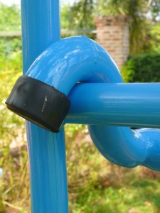
Chain attachment

Chain ladder is attached by welding on a piece of bent 1/4" rebar, flattened on the ends by pounding against an anvil.

Swing seat

Swing seats were made from 1 1/2" hardwood left over from building the house stairs, a 1" radius cut on the outside corners, and rounded off top and bottom with a 1/8" roundoff router bit

Seat Attachment

Chains are attached to seats with 1/4" threaded rod, bent to shape and welded at the top as it was too brittle to make the sharp bend. Carabiners were purchased at a local hardware store.

Seat Bottom

Nuts were welded in place to hold wooden seats on the stirrups. Can't afford a failure in use here.

Swing Chain Attachment

Swing chains were attached same as the chain ladder

Slide Attachment

Slide slips over a crossbar of the swing frame. Ends are capped with rubber feet available off the shelf.

Bottom Corner

Bottom crossmembers used square instead of round tubing to spread the load better. Ends were capped with rubber feet available off the shelf. Also welded on tiedown lugs from the local hardware store.

Slide Surface

To make it slippery I sanded the slide with 1000, 1200, and 1500 grit wet-or-dry sandpaper, then polished with two coats of fiberglass mold release wax. It's really slippery.

Test Project: Children’s Slide

Frame for slide

Slide frame welded from bent tubing

Wire Support

Chicken wire was welded to the frame and bent into position to hold the fiberglass in place while the resin cures.

Fiberglass Cloth

Fiberglass cloth is cut to size and laid in place.

Resin Applied

Polyester resin is applied

Slide Bottom

Resin cured too fast due to a) no data sheet b) language barrier and c) confused salespeople

Bottom Fiberglassed

After attempting to smooth out the bottom with body putty, I ended up fiberglassing it in for appearance and safety

Slide Puttied

The top of the slide after several layers of 2-part body putty and red glazing putty, sanded and ready for primer.

Primer Applied

Primer applied with spray gun

Bottom Painted

2-part epoxy top coat sprayed on bottom of slide

Top Painted

2-part epoxy sprayed on top. I love this paint (Jotun Penguard Enamel).

Top Close-up

Close-up of finished topcoat, Jotun Penguard Enamel, sapphire blue, 2-part epoxy