Building the Front Wing & Mounts

Front Wing

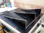
Finished front wing on the car (endplates to be added after setting ride height)

Fabricating a Formula 1000 Race Car Diffuser

Diffuser

Finished diffuser mounted on car

I try to post updates only for completed projects, and since I’ve had several projects in progress it’s been a while since I’ve blogged. The diffuser is finally finished, so here are some pix and a video that explains it all:


Building the Undertray / Floor

Finished Undertray

Finished undertray after painting rests in the mold for curing

Building the undertray started with building a surface large enough to hold it. It’s larger than it looks, so we had to laminate  decorative plastic laminate onto two 4×8 foot sheets of plywood that had been trimmed to about 3×8 feet each. Then wood to form the side air dams was screwed down, and the radii filled with auto body putty. Next we cut plastic honeycomb and plywood pieces to fit, with the plywood located to pick up the attachment points on the frame and to protect the radiators on either side of the car. I built a hot-wire foam cutter from a tree saw handle, a piece of guitar wire, and an automobile battery charger, which I used to cut foam profiles for the leading edge of the floor. Then we laid the whole thing up with epoxy and two layers of fiberglass on the bottom and one on the top, and vacuum bagged the whole shebang. Vacuum bagging was made more difficult by the random tiny holes in the plastic sheeting, which we expediently fixed by adding a whole second sheet on top of the first.

After debagging we painted it and found out the hard way that you can’t paint enamel over fresh epoxy in a humid climate. It never dried, and had to be scraped off like tar. Epoxy paint worked much better. We then mounted the undertray on the car, drilling mounting points through the plywood in the correct places. We had to fabricate a mount for the front of the undertray, which was a little tricky as we didn’t want to remove the fiberglass body panel under the driver’s legs so everything had to be done from the outside. We fabricated a small pylon from aluminum sheet and pop-riveted and epoxied it to the bottom of the body.

Laying Up a Carbon-Fiber Honeycomb Front Impact Attenuator

Impact attenuator

Nose in place while epoxying aluminum hard points into correct positions

SCCA FB rules require a metallic or composite front impact attenuator. Can’t have cars running around on the track with a battering ram on the front… My impact attenuation structure, or crash box, consists of a carbon-fiber and honeycomb sandwich laid up directly on the inside of the fiberglass nose. The carbon fiber varies from four layers at the front to eight layers around the rear attachment points so that it will crush progressively from the front to the back. Cylindrical aluminum inserts are used in the honeycomb as hard mounting points for the wing to the nose and for the nose to the chassis. This area is designed to be strong enough not just to absorb impacts but to allow lifting the front of the car by the front wing.

Attaching the Body

Starting to look like a car

Almost finished mounting the body

Not much to say about this one… Just lots more piddly little brackets. The large bracket at the tail is necessary as that will be where the rear impact absorber will mount. Had to make some changes just behind the driver’s left shoulder to allow access to the fuel filler.

More Laser-Cut Parts and Panels

Laser Cut

Second batch of laser-cut parts.

I received my second batch of laser-cut parts, this time from a new supplier that has some more reasonable aluminum. They did a reasonable job, but man were they slow. It took three visits and more than two weeks to get a quotation, then I forget how long to do the work. Then when they were finished, I had to call them to find out. This is Thailand.

The parts are cut from both steel and aluminum of several different thicknesses, and include the radiator and oil cooler mounts, differential mounts, some engine mounts, the entire pedal cluster, parts of the steering column, chain tensioner, nose mounts, steering rack mounts, steering column mounts, lap belt mounts, chassis side panels, seat panels, the firewall, fuel tank, and even an idler sprocket.

Laser Cut Panels

Laser-cut panels including sides, seat and fuel tank

Part Eleventy-seven, In Which We Finally Lay Up a Body

Finished Body

Another view of finished main body.

Time to lay up the first set of body panels. In some photos you can see the joggles laid into the molds with duct tape so the panels will overlap smoothly. Nine coats of mold release wax and there were no problems releasing parts from the molds, although at times I did have to work a bit. Each mold required about a day of finishing work to remove ripples due to waviness in the body buck. As I’ve said before, don’t build a body buck the way I did it. Instead, immediately after completing the X-Y grid of cross sections, lay about 3mm of fiberglass on top to give a good solid surface, then use body putty on top of that. You’ll be finished in half the time it took me. The only place you should use foam is where actual carving is required due to the complexity of the shape, like the sidepod air inlets. Yes, I know the main roll hoop forward braces are still not there. Patience…

One problem I found out the hard way is that a chemical in some brands of duct tape inhibits gelcoat curing. In the end, gelcoat that had been in contact with some kinds of duct tape never fully cured and had to be cleaned out with acetone. Also, the joggles formed with duct tape were too sharp for the fiberglass mat to conform to, resulting in bubbles under the gelcoat that have to be scraped out and reworked. Gelcoat is probably more trouble than it’s worth given its weight, so next time I’ll just prime and paint the body panels to finish them. The sharp joggle corners need to be filled in with fiberglass roving before laying mat on top.

Last of the Molds

Mold Set

Completed set of molds

Since this is the last of the molds, in the photos below I’m showing each of the layups, for a total of three. Target thickness for the molds is 4.8mm, three times the expected thickness of the parts to be molded.

Fiberglass Mold Layup, Parts 4, 5, 6…

Probably the main thing to explain here is how I create the overlaps in the molds. The edge of a mold is marked on the body buck with duct tape, which will leave an impression in the mold for later trimming of the finished part. Then after removing the mold from the buck, I lay in a strip of 1″ duct tape touching the existing tape, then another strip touching that one. I then remove the first two strips of tape, leaving the edge for the next mold with a 1″ overlap.

Fiberglass Mold Making- Nose, Tail, Sidepod

Time to make molds!