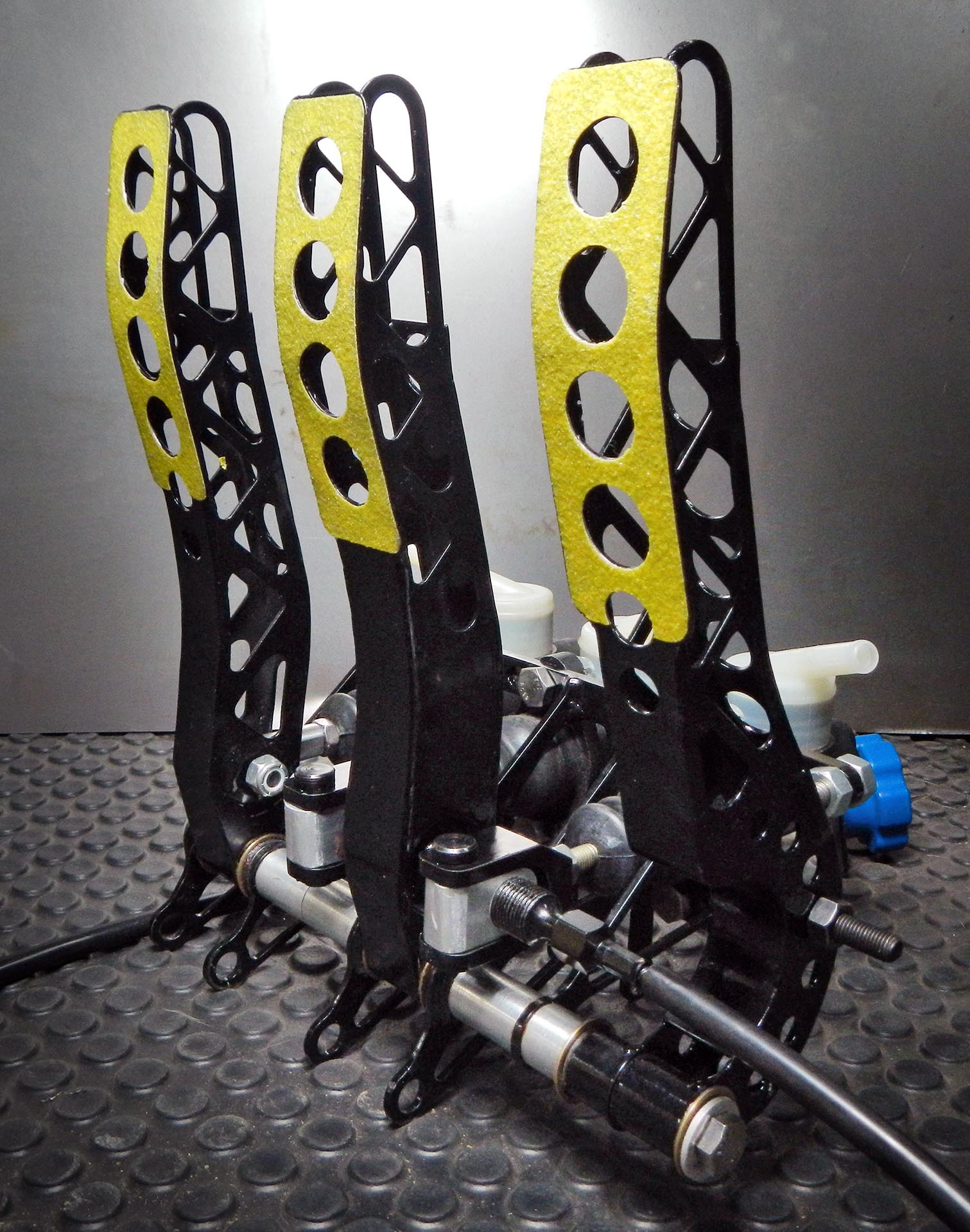
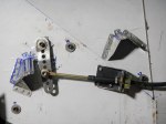
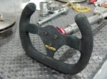
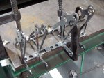
Finished pedal cluster
Here’s a big project that spread out over a number of months. I’m aggregated the photos here and attempted to make them tell a coherent story.
The cluster as a whole can be adjusted forward and back for drivers of different heights. The gas pedal is adjustable for foot travel, throttle cable travel and left/right position. The brake pedal height is independently adjustable, and brake bias is adjustable from front to back. The hydraulic clutch pedal is also independently adjustable for height.
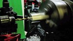
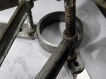
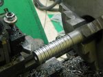
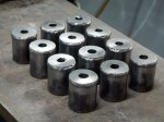
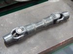
Many of the original pieces were laser cut from steel, then bent and welded to form the complex shapes required. Some of the bushings were CNC turned, but most were made by hand. The master cylinders, brake bias adjustment cable, and the nuts and bolts were purchased, with everything else custom made. This includes the brake bias adjustment assembly, which forced me to learn how to cut threads on the lathe. It’s not as easy as it looks. Take a look at the brake bias adjustment bar– it has three sets of threads independently cut on a manual lathe, three diameters, two snap rings and a threaded hole. Good fun! Due to changes in the steering rack mount, the main pedal bracket had to be widened as you can see in the photos.
-

-
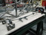
Laser cut parts arrive
-

-
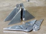
Laser cut gas pedal parts before welding
-
-
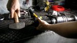
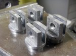
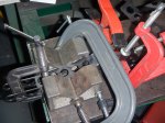
Gas pedal parts clamped for welding. I like clamps.
-
-
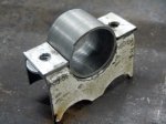
Clutch pedal clamped for welding
-

-
Clutch pedal after welding and grinding
-

-
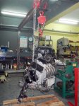
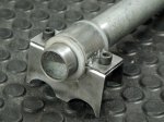
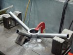
An early trial fitting
-

-
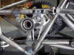
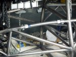
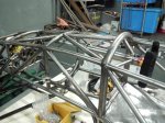
Testing fit inside the frame
-
-
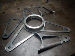
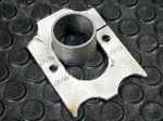
Widening the main bracket
-

-
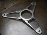
Finished main bracket
-

-
Lots of parts in primer now fitting together
-

-
Black epoxy paint
-

-
Finished except for brake bias assembly
-

-
New Chinese calipers: 2″ = 51.9mm LOLWUT?
-
-
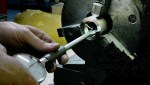
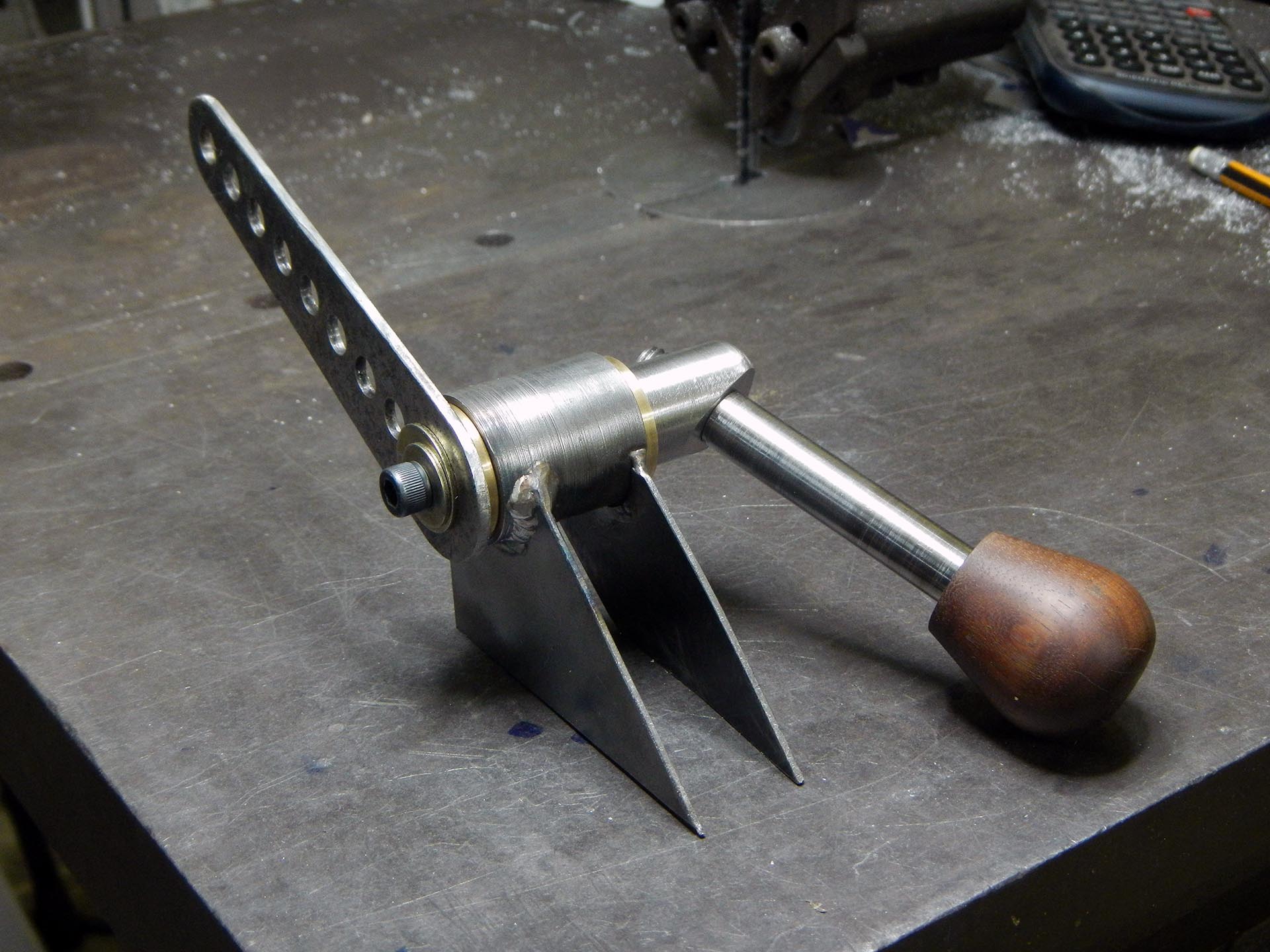
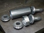
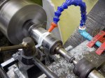
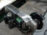
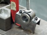
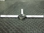
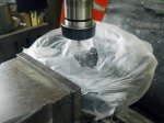
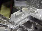
Milling part of the brake bias adjustment bar assembly
-

-
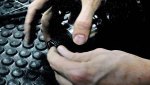
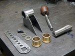
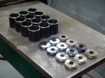
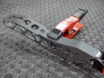
Brake bias adjustment parts

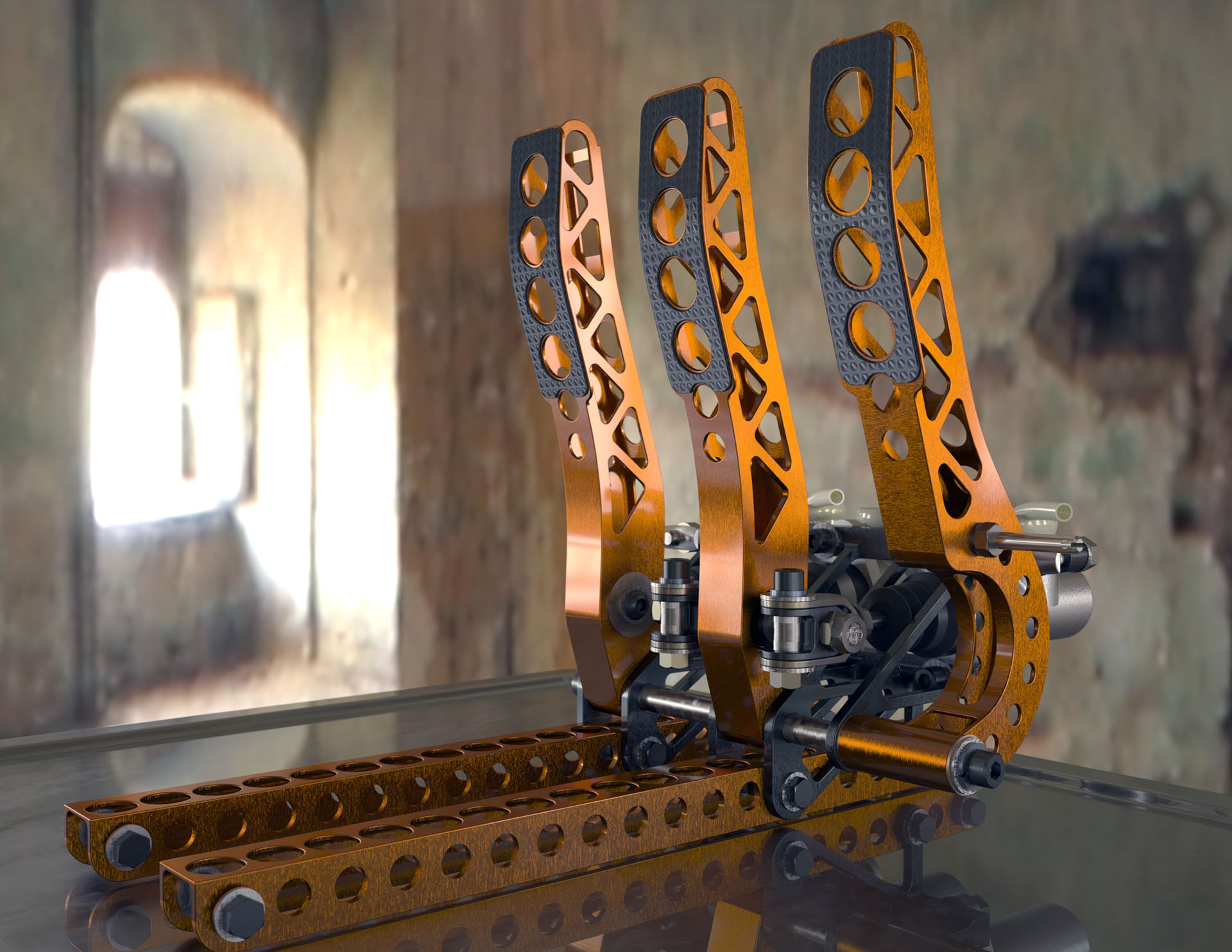
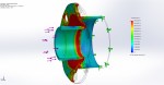
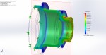
Computer rendering from early 2011