Fabricating the Pushrods & Upper A-Arms / Wishbones / Control Arms

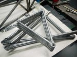
Finished

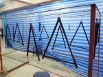
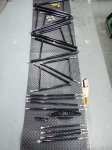
Finished set of control arms, tierods & pushrods

The upper control arms are all identical except that the bearing cups are mirrored from the left to the right so that the snap rings are on the bottom. If I can find a way to stake the spherical bearings then all four could be identical. Staking is a process that uses a hydraulic press to deform the bearing cup into a chamfer around the circumference of the spherical bearing, holding it permanently in place.

I printed out the layout of both control arms onto size A0 paper, glued the paper to a sheet of plywood, and drilled holes for the centerlines of each rod end and spherical bearing. This gives me a jig I can use for tack welding the parts in place. Washers under the bearing cups locate them vertically for tacking. The bearing cups proved a little too thin to weld without distortion, so I had to re-cut the spherical bearing bores after welding. Luckily I have an indexable end mill of just the right diameter, and running my mill at high speed with a lot of coolant gave a good finish on the bores. I then pressed the spherical bearings into place before painting as I wanted to make sure there were no glitches that would require messing up the paint to fix.

I sprayed Jotun Penguard 2-part epoxy paint directly onto the steel after first making sure the steel was scrupulously clean with a Scotchbrite pad on an angle grinder, followed by a cleaning with acetone and paper towels. The finish came out beautifully.

The Build Begins– The Front Subframe

After more than a year and a half of design and several months of tool preparation, that long-awaited day has finally arrived: the day I touch saw to metal on an actual car part. The first step is to build the front subframe that sell sit horizontally at the bottom of the nose of the car. The chassis table already has holes drilled and tapped for 3/8″ bolts locating the subframe members precisely. Here’s the first tube in place among the pins on the chassis table.

First Tube

First tube in place on the chassis table, bent to fit pins

First Weld

Lower front frame member cut to fit and tack welded in place

Finished Subframe

Finished front subframe, fully welded. Since it's laterally symmetrical, it's flipped over to weld the bottom.

Subframe on jigs

Front subframe raised to final position, supported by chassis jigs. Note Natural-Polymer Swing Press at right. A useful tool.

Building the Chassis Jigs

Scrap Jigs

First "professional" jigs

Because this looked like a lot of busy work, my first thought was to have the chassis jigs built by a local machine shop. So I bought the metal and had it sent directly to the machine shop and went over the drawings with them. They kept asking me how big various things were, when the dimensions were clearly right there on the drawing. Then it became clear they didn’t know how to deal with dimensions in meters. They asked me how to convert a dimension from meters to centimeters. “You mean like move the decimal point two places to the right?”, I’m thinking… This was not looking promising. Eventually I went home and tried to come up with a set of orthographic-projection drawings, with hidden lines removed, that they couldn’t possibly misinterpret. I soon gave up. When I went to pick up the first two jigs the next day, the list of errors was long and creative. Mounting footprint on one reversed, vertical tube holders cut too shallow and not in line, overall height incorrect, horizontal alignment out of spec, etc., etc.

Sigh. I called a local aerospace-engineer type that I know and asked him if he knew a good machinist, and he directed me to a local guy who I visited the next day. We met a couple of times and he is indeed capable of handling the project; in fact, I decided it’s really below his capabilities and ended up building the jigs myself, saving him for building actual car parts.

Cut Pieces

Lots of cut pieces waiting for welding, drilling, & milling

I needed a good, strong right angle to hold the pieces in place while welding. The bandsaw table served perfectly.

Welding Jig

Welding the angles onto the uprights. Chassis table is very useful here.

Drilling Crossmembers

Drilling the chassis table crossmembers on the milling machine.

Trial Fit

First trial fitting of the chassis jigs onto the chassis table. Top rail guides not yet cut; other tube guides not yet in place.

Welding Verticals

Welding tube guides for vertical tubes. Sample tube keeps things in alignment, along with very careful tack welding.

Jig Set

Almost-finished complete set of chassis jigs

Subframe Pins

Chassis table crossmembers were drilled for pins to hold front subframe during welding.

Stretched Bolt

3/8" bolts should be tight. But not this tight.

Designing the Chassis Jigs

Frame on Jig

Chassis in place on chassis table with all jigs in place

I had been trying to keep the chassis jigs in my head, but finally decided they’d probably come out better if I put them on paper first. So I spent the past few days designing them, and it became quite clear why I couldn’t keep them all in my head. I intend to bend the top chassis rails in one continuous curve as that will add a lot of style to the chassis. A lot of race car frames look like industrial equipment, but I have something in mind more like an Ariel Atom exoskeleton car, where the frame is so beautiful you don’t even need a body. Of course the car will have a body for aerodynamic, esthetic, and safety reasons, but I’d like people to see the frame without the body and still say “Wow!”. Now, the top rails are splines, not just arcs, and the only way to really bend one properly is to know where it’s supposed to be in 3-d space along it’s length, and that’s where the chassis jig comes in. When the chassis jigs are all in place, it will give me target locations all along the length of the frame that I can bend the rail to fit.

I eventually ended up with 22 pages of drawings that look like this:

Sample Jig

1 of 22 chassis jig drawings


And two pages of drawings that look like this:

Cross Rails

Sample chassis jig cross rail drawing

Lower Front A-arm Front Attachment Point

Front Suspension Jig Point

Lower Front A-arm Front Attachment Point

The first jig hard point will be the lower front A-arm front attachment point. This may look a little odd if you’re only acquainted with street-car derived race cars, as the lower front A-arms almost meet in a point under the car, much like a Formula 1 flexure. This gives the suspension the optimum geometry for minimal camber change under body roll, and is part of the reason street-car based race cars can’t come close to the performance of a purpose-designed formula race car. The jig attachment point is fabricated from 3″ x 1/4″ steel C-channel, cut to the basic shape with the plasma cutter, ground with an angle grinder closer to its final shape, then the reference faces were milled on the milling machine to an accurate final shape. Then I turned up a small cylinder like the one that will be welded into the chassis, to serve as a spacer to locate the braces when they are welded to the chassis table. In the photo, the braces have not yet been welded to the jig crossmember.

Table Damage

Plasma cutter erodes concrete tabletop

In the process, I learned something not to do with the plasma cutter. I laid the C-channel on a concrete table for cutting, and the plasma stream went straight through a quarter inch of steel and seriously eroded the concrete. Hard to believe this took only seconds to happen!

The plasma cutter is an amazing tool. Cutting through this much steel with a 14″ portable cutoff saw, well, after 15 minutes I gave up. Once you know what you’re doing with the plasma cutter, a cut like this takes only 10-20 seconds.

Plasma Cut Edge

Raw edge cut by plasma cutter


Here’s what the raw cut edge looks like. Those ripples are from the shaking of my hands as I move the cutter. When cutting, you feel no resistance at all, but if you go too fast the cut won’t go all the way through the metal. When first using the plasma cutter, it took me a while before I figured out what I was looking at. The welding helmet has to darken so much, and the plasma is so bright, that you can only see a tiny area around the beam. Eventually I figured out that, if you view from the right angle, you can see the actual beam which is as narrow as a needle. Once you can see it you can control it better.

Building the Chassis Jig Table

Chassis Jig Table

Chassis Jig Table

As I plan on building many of these cars, and they must all be exactly identical, I have to start with an absolutely flat, true, square, level, solid and repeatable surface. To that end I designed this chassis jig table out of 3″ and 4″ x 1/4″ steel C-channel. Over 500 pounds of it. I initially started the gardener off cutting steel, and although I told him it had to be perfect, 45 degrees seems to mean anywhere between 43 and 47 degrees to him so that didn’t work.

Next I hired my long-time Honda repair & upgrade mechanic to work for me full time, but he mysteriously stopped showing up for work and his phone stopped working after a week or two so I ended up building the table myself.

Anyway, now I know the table is as perfect as hand tools and my milling machine can make it. I figure it’s plus or minus less than half a millimeter over its length of 3.3 meters. The table sits on eight 5/8″ bolts that serve as adjustable feet, and in adjusting the table I found out just how out of level the concrete floor of the operating room is. I figure if I really want to make it perfect, I can flood the pit you see in the photos so the surface of the water is exactly level with the surface of the table, but that might be excessive.

Painting

Painting the chassis jig table

This was also a good chance to practice my welding. The Thais think TIG welding is exclusively for stainless steel so I didn’t even bring up the idea of TIG welding 1/4″ steel channels, for which they would use plain old arc welding. I bought a fancy 200-amp all-adjustable TIG welder, the most high-end one I could find locally, but the sales staff said Thai people don’t use the pedal controls and so they are unavailable in Thailand, even though the plug for the pedal is clearly visible on the front of the unit. Unfortunately all the TIG welding videos and tutorials I can find on the web pretty much assume you have a pedal control. After I got chased out of another welding store for riffling through their plasma cutter tips, looking for one that fit my machine, I decided it might be easier to just look on Ebay US. What do you know, I found everything I need from a supplier in China. So I ordered from my computer in Thailand, on the US Ebay site, from a vendor in China, and paid with PayPal, and the supplies arrived before I expected them.There was a bit of a problem clearing customs as they didn’t believe the invoiced value on the box ($13, heh, heh), but DHL took care of everything and found my house without me giving them any directions. That’s a first.

TIG welder foot pedal

TIG Welder Foot Control

And what a difference the pedal control makes! What was previously almost impossible becomes fairly easy. Now I think I’ll get some more practice by welding up some playground equipment for my daughters.

In case anybody needs it, here’s a free copy of the chassis jig drawings, four sheets of size A0 in PDF form. I just uploaded this file again as there was an error on the first page of the previously uploaded file, so anybody who downloaded the file before September 11, 2011 might want to get the latest version where you can see the top-level isometric view on the first page.

Also, note that there have been a couple of changes since this drawing was made. The holes for the feet are spec’d for 3/8″ bolts, but I upgraded them to 5/8″ (15.88mm).

Drawing Thumbnail

Download Free! Chassis Jig Drawings

Then, while building the table, I found it was a little hard to adjust without some diagonal bracing to hold it in place while attaching the top crossmembers. I added the diagonal braces you can see in the photo, made of 1/2″ x 1/2″ x 0.062″ square tubing, pounded flat at the ends, drilled, and bolted to the tops of the leg assemblies with 1/4-20 bolts. This way I could adjust the table for squareness and it wouldn’t change when I tightened the top crossmember attachment bolts.