Building the Chassis Nose

Starting Nose

Starting the nose tubes.

More Tubes

Test fitting the A, C, & D bulkhead side and bottom tubes.

Adjusting Jigs

Adjusting the jigs to fit as I go. Have to make sure they can be removed after welding.

Top Tubes

Test fitting the C to D bulkhead top tubes

Tube Rippling

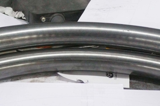
Top tube: seam on inside of bend. Bottom tube: seam 45 degrees from inside of bend. Note slight rippling on upper tube. This is why seams must not be located on a major axis of bends.

Front Roll Hoop

Front roll hoop ready for welding.

Front Roll Hoop Done

Front roll hoop fully welded.

Better Weld

Welds are getting better. Now as long as I don't have to stand on my head I can make a pretty good weld.

Front Roll Hoop in Place

Front roll hoop in place. This required cutting the top tube frames. Not a problem as each piece will retain the correct shape.

Starting to Weld

A to C bulkheads welded. There is no B bulkhead (:-).

A, C, & D Bulkheads Welded

A to C to D bulkheads welded

Front Roll Hoop Welded

Front roll hoop welded, top diagonals added.

D-E Sides

D to E side diagonals added.

Nose Finished

The basic frame of the nose from the tip to the front roll hoop, finished.

How to Fishmouth Tubes in Solidworks

After playing around with various kinds of hole cutters, mills, angle vises, and so on, I’ve settled on the best method for cutting fishmouths in tube ends so they fit together properly when building a tube frame with round tubing. Since the tubes will be welded they don’t have to be perfect as you would get by using a milling machine. Also, the typical joint has several tubes meeting which need to accomodate each other, and on a milling machine this would take a separate setup for each tube at each joint, taking an inordinate amount of time. Forcing Solidworks to show the correct shape of the ends of each tube requires some real work, an explanation of which I found over on the LoCost website. I’m going to provide a modified and updated tutorial here.

The first thing to understand is that each tube must be fully welded before adding the next tube. This makes the finished structure much stronger than if you tacked all the tubes in place and simply welded around the remaining visible joints. Here’s an example:

Welded Joint

In a multi-tube intersection, the first two tubes are fully welded before adding the next tube

Third Tube

Third tube in place before welding

Third Tube Welded

Third tube fully welded

Solidworks Tutorial

Although the following tutorial may look long and complicated, once you understand what’s going on each step will only take seconds. And believe me, it’s much faster than grinding a tube to fit using trial and error. More accurate, too.

Weldment Profile

First, create a weldment profile with the correct outside diameter, a thickness of 0.1mm, and a gap of 0.1mm as shown.

Original Weldment

Original weldment use a profile of 25.4 x 1.0 mm round tube

Replace Profile

Replace this with the new, slitted profile
Check Trim

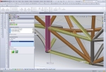
Each tube will need to be trimmed to the tubes around it, reflecting the order in which they will be assembled. Insert > Weldment > Trim/Extend. Check your trims.

New Part

Select the tube, right click and choose "Insert into new part".

Save Part

Save the part with a descriptive name. I keep a separate directory of tubes.

Sheet Metal Bends

Select an INSIDE EDGE and click Insert>Sheet Metal>Bends.

Click OK

Just click the green check mark. No need to fiddle with any options.

Suppress Bends

Right click on "Process Bends" and choose "Suppress".

Flattened Tube

And you get a flat sheet.

Get Normal View

Select he surface and choose a normal view
Normal View

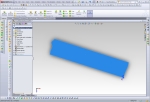
With a Normal View, dimensions and shapes will be correct.

New Drawing

Open a new drawing and insert the current model view.

1:1 Scale

Set drawing scale to 1:1, full scale

Rotate View

Right click on the drawing view and choose Drawing Views > Rotate View.

Rotate View

Through trial and error, figure out how much to rotate the view so that it is horizontal.

Now Horizontal

Now we have a horizontal drawing view.

Insert Another

Insert another drawing view...

Current View

Also of the current model view.

Rotate Again

Rotate the view as before to get another horizontal view.

Two views

Two views on one drawing.

Align Horizontally

Align the views horizontally by right clicking on one view and choosing Drawing Views > Align Horizontally by Origin.
Draw Rectangle

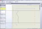
Crop each view by first drawing a rectangle with 4 lines. The automatic draw rectangle won't work because it uses the unrotated axes.

Crop View

Crop the view by selecting the four lines of the rectangle, right click and choose Drawing Views > Crop View

Shortened Tube

Now we have both tube ends with the middle removed, fitting on a single A4 sheet.

New Sketch

Now we need a reference for how far the ends of the tube are from each other. Go back to the tube part and create a sketch like this.

Extrude Cut

Using the sketch, extrude a cut through the part and keep all bodies.

Cut Part

The part now looks like this.

Drawing Annotations

Go back to the drawing and add annotations as necessary for use in the shop.

Save as PDF

Save the file as a PDF and print it out on sticker paper. Cut out the 2 ends and stick them on the tube at the indicated distance. Use an angle grinder to grind to the lines.
Calculating the Loads on the Front Suspension

Suspension FEA

Simplified left front suspension finite element analysis result

It’s time to finalize my parts order, which means I have to pick all the rod ends and spherical bearings for the suspension. Up to now I’ve relied on rules of thumb, which isn’t good enough for a state-of-the-art race car. So I simply opened up one of my higher-level chassis models in Solidworks, one with most of the suspension attached, and created a 3D sketch of the upper and lower left front suspension A-arms, constraining the endpoints of the lines to the centers of the rod ends and spherical bearings. Then another line to simulate the upright and tire, and I’m done with the sketch. Then I created a structural member along each line and opened a static simulation study. In the study I constrained the inboard ends of the A-arms to zero translation and applied a 1400 pound load toward the rear of the car to simulate 4-G braking. Run the study, and voila! axial loads on each member.

Upper Front: 785 pounds

Upper Rear: 1211 pounds

Lower Front: 2639 pounds

Lower Rear: 3096 pounds

This allows me settle on 1/4″ rod ends for the inner upper attachments, 3/8″ for the inner lowers, a 7/16″ spherical bearing for the upper ball joint, and a 5/8″ one for the lower ball joint. All chrome moly alloy. Even these are far stronger than indicated necessary by this analysis, but I don’t want to deviate too far from standard practice on this design. Maybe transitory loads can be far higher?

Calculating the Loads, Round II

At the urging of a poster on ApexSpeed.com who insisted my calculations were inaccurate due to the non-zero joint stiffnesses, I re-ran the analysis with the suspension a-arms modeled as trusses. A truss model allows only axial loads on a member, using hinges at both ends to zero the moments. This gave me results that were the same +/- 2%, which makes no difference given the uncertainty in estimating the operating loads.

However, I also refined my model to include the suspension pushrod and that did indeed give me a different result. With the pushrod in place I could model the vertical load due to the weight of the car and the aerodynamic downforce. I’m now working with a braking force of 1600 pounds and a vertical load of 1230 pounds, which assumes a coefficient of friction of 1.3 for the tire on the surface of the track. This gives me the following axial forces:

Suspension

Left front suspension modeled as a truss with pushrod

Upper Front: 1103 pounds

Upper Rear: 1258

Lower Front: 4432

Lower Rear: 2366

Pushrod: 2357

Note that including the vertical load and increasing the braking load shifted the most highly-loaded member from the lower rear to the lower front, and increased the maximum load from 3096 to 4432 pounds, or 43%. The chrome-moly 3/8″ rod ends I’ve specified for the lower a-arm inboard joints still have a safety factor of 2.14 under these conditions. The posters on ApexSpeed have strongly warned me against using 1/4″ rod ends in the suspension, so existing inventory will be used in a different application and the upper rod ends will be upgraded to 8mm. It appears that only metric rod ends are available locally. Under these assumptions the pushrod rod ends will have to be further upgraded to 10mm, although I hate to have a whole separate part for just the pushrods, so I’ll have to re-examine the assumptions.

By the Pricking of My Thumbs, Something Wicked This Way Comes

Bwahahahah!

A mysterious form begins to take shape on the slab

Now it’s time to test one of the big unknowns of this project: can the top rails be formed in the shape of a complex 3D spline, and can the left and right sides be made to match? The CAD software won’t even allow a structural member in the shape of a spline, requiring them to be composed of straight sections and arc sections. Other exoskeleton cars have been built, but as far as I know always with a single curve in the main frame members. And of course a tubing bender is designed with the assumption that it will be used to form constant-radius segments. I believe this is the first car to be done this way, so I’ve put a lot of effort into the chassis jigs to get it right. The top rail spline is a key to the beauty of this design. To make a long story short, it is in fact possible to bend a 3D spline on a tubing bender. It just takes a lot of trial and error, patience, and about a day of work per rail. And luckily, overbending can be corrected by running the tube back through the bender, clocked 180 degrees.

“The pricking of my thumbs” is not entirely rhetorical. In fact I almost cut off my left thumb while building the top rails, so a word about safety. A tubing bender is a SERIOUS PIECE OF EQUIPMENT. It won’t even notice bones and flesh being fed into its’ rollers. I had already turned off the bender and reached to grab the tube as it was twisting on the way into the bender. The bender caught my glove and started pulling my thumb in, stopping at the last possible millisecond before inflicting permanent damage. It hurt and left a mark, but I was insanely lucky. So, 1.) Never wear gloves while using a tube bender. They protect you about as much as Saran Wrap, and it’s better to have your fleshy appendages dangling about unprotected to remind you of the danger. 2.) NEVER, NEVER touch the tube on the side being fed into the bender. Always handle the side being fed out. and 3.) Before pushing the “on” switch, stop, think, and say to yourself  “I’m not going to become an amputee on this bend.”

Straight tube

So here's the problem: how do we make this straight tube fit all those notches located in 3D?

Half Done

Left top frame rail about half done

Left rail done

Top left frame tube fitted to chassis jigs

2 Top Tubes

Both top frame tubes bent to shape and matched to each other, in place on the chassis jigs. Now it's possible to get a feel for the size and shape of the car. It's really going to be beautiful!

Really Light

The main frame rail, running from the front to the back of the car, is so light I can lift it with a single finger.

Vroom, Vroom

Sitting inside the chassis for the first time. Time to make vroom vroom noises.


Building the Front Keel

To get optimal suspension geometry and aerodynamics I’ve designed the car with a front keel under a raised nose. This gives the longest possible lower front A-arms, minimizing the angle changes of the front suspension as it goes through bump and jounce motions. The raised nose clear airflow around the front wing. My computational fluid dynamics (CFD) studies show airflow around the front wing is extremely important as the wing operates in ground effect and generates downforce all out of proportion to its size. I spent a considerable amount of time trying to increase the downforce generated by the underbody and rear wing to match that of the front wing, even though those elements are far larger.

The front keel will use a stressed skin of aluminum formed to shape and riveted to tabs welded onto the frame tubes. This is the highest-stress area of the entire chassis, as under braking something like 2800 pounds of force will be transmitted through these members. You can visualize the car supported vertically on the front keel, with two more cars stacked on top of it, so this needs to be really strong.

Front Keel Tube

Front keel tube is drilled on the milling machine for front lower A-arm attachment points. This will give perfect mounting locations.

A-arm Attachments

Lower front A-arm attachment points were cut and drilled on the lathe, then tapped.

Welding Setup

Chassis table comes in handy again for welding the lower front A-arm attachment points into the front keel tube.

Finished keel tube

Completed front keel tube assembly. Front lower A-arm attachment points welded in place, ends of keel tube capped for strength.

Keel Tube in Place

Front keel tube assembly rigidly located in place on chassis table.

Tube Bender Scrap

The 3-roller tube bender generates about 65 cm of scrap at each end on small-radius bends before it starts generating the correct constant -radius bend.

Keel down-tube

First front keel down-tube in place. The surface of the keel will be concave to let air flow better across the upper surface of the front wing, necessitating curved tubes to hold the keel.

More down-tubes

More front keel down-tubes. The two rear tubes are a recent addition to the design as this area needs to be phenomenally strong and the tubes weigh almost nothing.

Finished Front Keel

Finished front keel and front subframe

The Build Begins– The Front Subframe

After more than a year and a half of design and several months of tool preparation, that long-awaited day has finally arrived: the day I touch saw to metal on an actual car part. The first step is to build the front subframe that sell sit horizontally at the bottom of the nose of the car. The chassis table already has holes drilled and tapped for 3/8″ bolts locating the subframe members precisely. Here’s the first tube in place among the pins on the chassis table.

First Tube

First tube in place on the chassis table, bent to fit pins

First Weld

Lower front frame member cut to fit and tack welded in place

Finished Subframe

Finished front subframe, fully welded. Since it's laterally symmetrical, it's flipped over to weld the bottom.

Subframe on jigs

Front subframe raised to final position, supported by chassis jigs. Note Natural-Polymer Swing Press at right. A useful tool.