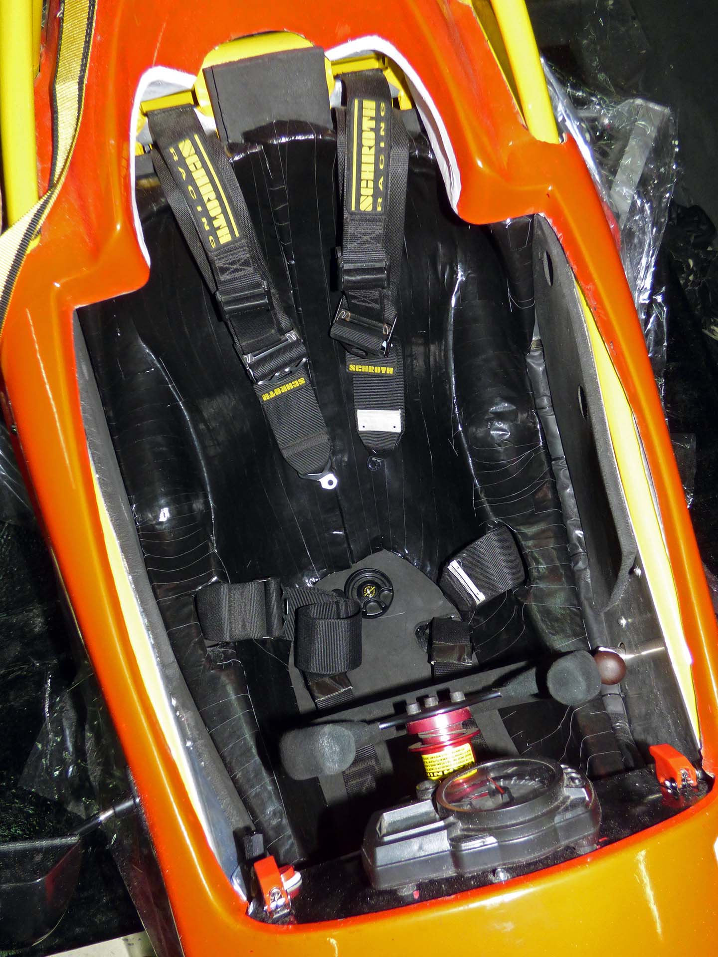
Finished Seat
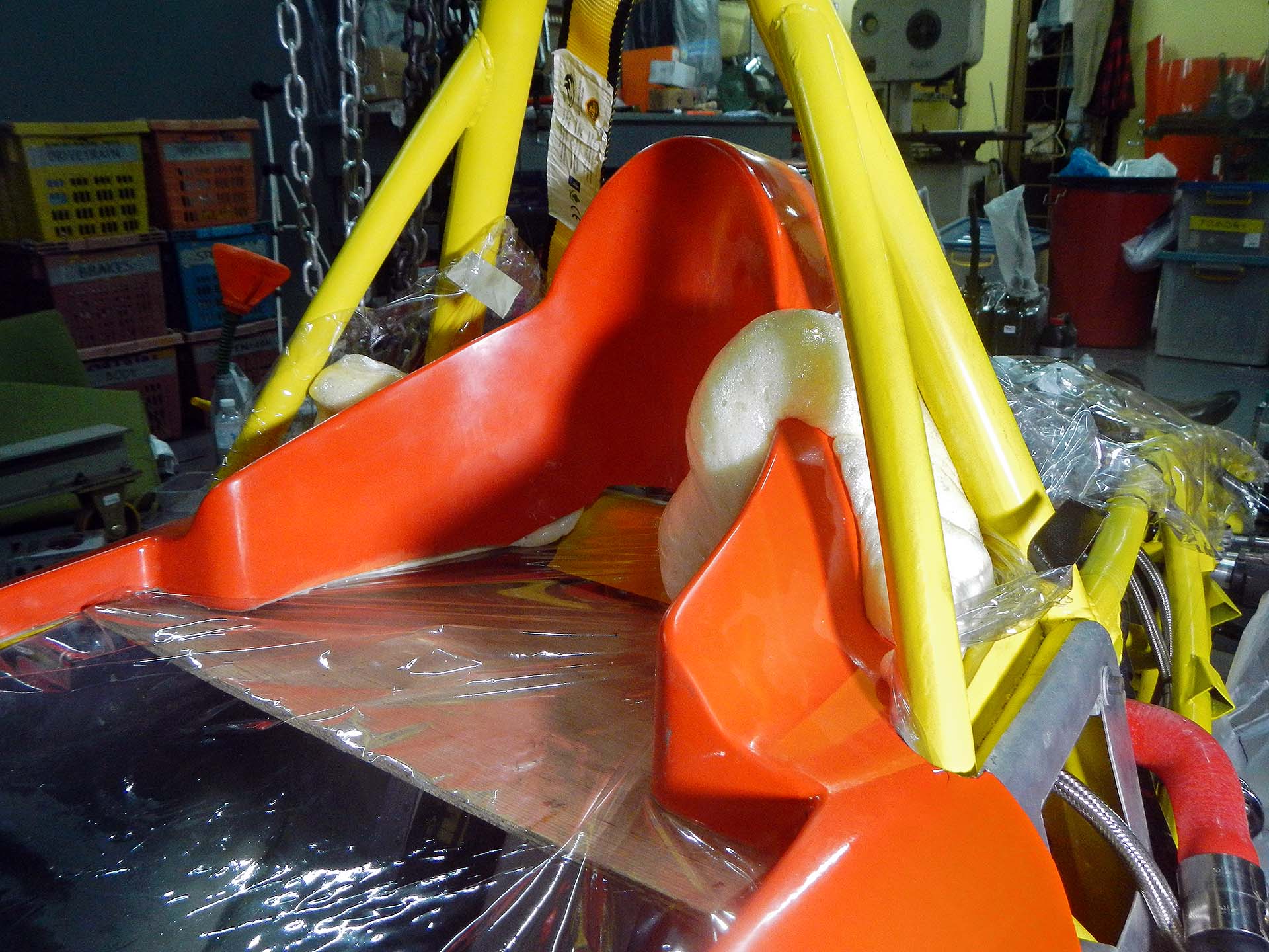
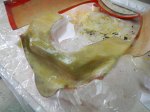
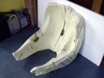
For the intermediate term I’ll be using a custom-molded seat insert made with readily available (and cheap) two-part urethane foam. I have a kit of the Indy/F1 style foam, but it’s so expensive I’m going to learn what I can from the cheaper seat first. I’ve learned useful things already: on the first pour the bag doubled over or stuck to itself and the foam didn’t make its way to the thigh area, so the first attempt was scrapped. It was also useful, however, in finding out where to slice the foam to get it out of the car easily, and learning how thin the foam will make itself under high pressure areas (zero thickness). So for the second attempt I first lined the entire cockpit with two layers of 10mm energy-absorbing foam before pouring the 2-part foam.
As it expands the foam pushes hard against any constriction, like your body. When it hardens it’s almost too tight to fit back into. Many hours of sanding and cutting are needed to make the fit reasonable and comfortable. As it is, I can’t even get into the seat with my wallet in my pants pocket. At first I couldn’t even breathe in fully with the shoulder harness straps moderately tight.
-
- First attempt was a learning experience as the foam didn’t go into the thigh area
-

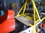
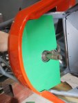
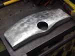
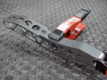
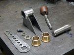
- Plastic template for main foam piece
-
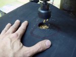
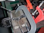
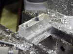
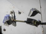
- Using a hole saw on the drill press to make anti-submarine strap cutouts
-

- One of two finished main foam pieces
-

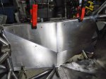
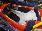
- Lots of energy-absorbing padding
-
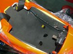
- Another view of the default foam padding
-
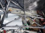
- Pouring bag made from 2 XXL garbage bags taped carefully together for no overlap
-

- Sanitized for your protection
-
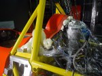
- The pour happens very fast
-
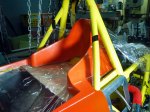
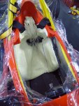
- Immediately after the foam pour
-
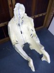
- Sliced down the middle at an angle for easy removal
-

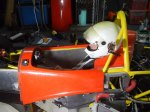
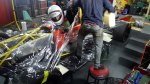
- One of many test fittings, complete with HANS device
-
- Lots of sanding and cutting to make it correct
-
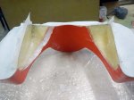
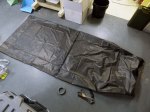
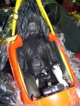
- Finished foam pieces ready for taping
-
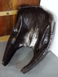
- Covered with black duct tape