
I finally found a video that conveys the full speed available from a Formula 1000 race car, a Gloria F1000 doing a hillclimb in Italy (skip forward to 3:15). THIS is why I’m building a race car:
Monthly Archives: December 2013

Last of the Molds
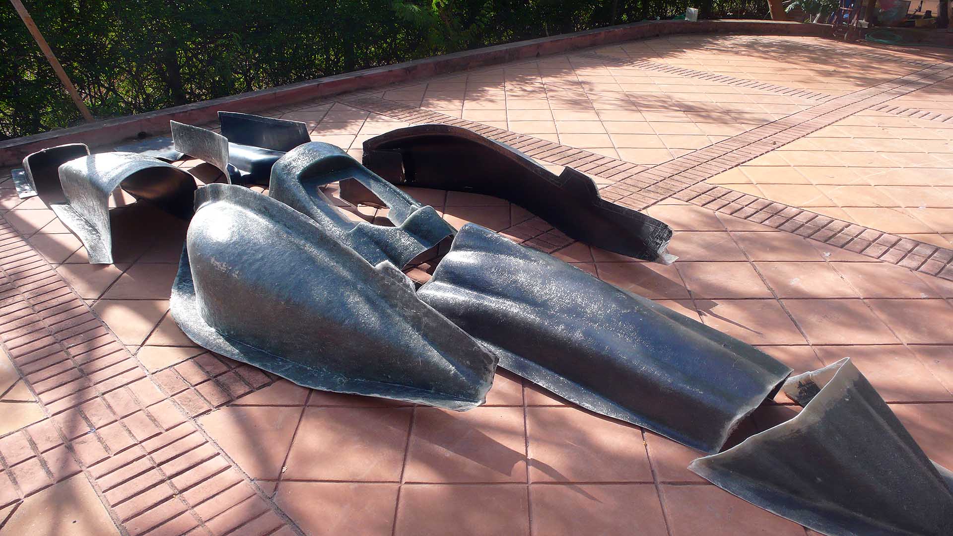
Completed set of molds
Since this is the last of the molds, in the photos below I’m showing each of the layups, for a total of three. Target thickness for the molds is 4.8mm, three times the expected thickness of the parts to be molded.
-

- Keel gelcoated
-

- 1st layup
-

- 2nd layup
-

- 3rd layup
-

- Mold released. Some sticking on bottom of keel.
-

- Cleaning the mold. Comes off easily with a scraper.
-

- Completed set of molds
-

- Another view.
-

- Sanity check– test fitting molds on the chassis.
Fiberglass Mold Layup, Parts 4, 5, 6…
Probably the main thing to explain here is how I create the overlaps in the molds. The edge of a mold is marked on the body buck with duct tape, which will leave an impression in the mold for later trimming of the finished part. Then after removing the mold from the buck, I lay in a strip of 1″ duct tape touching the existing tape, then another strip touching that one. I then remove the first two strips of tape, leaving the edge for the next mold with a 1″ overlap.
-

- Left sidepod waxed 10 times and marked
-

- After first layup
-

- After second layup
-

- Right sidepod mold released
-

- Body buck prepared for engine cover layup
-

- Engine cover gelcoated
-

- Rolling out the bubbles
-

- Catalyzed polyester resin. Color change after stirring vigorously for 1 min.
-

- Brushing resin onto fiberglass mat
-

- Engine cover layup finished. Molds are about 6mm thick.
-

- Released engine cover mold
-

- Body buck after mold release
-

- Tape detail showing how overlaps in molds are created
-

- Leg cover gelcoated
-

- Leg cover fiberglassed
-

- Cockpit gelcoated
-

- Laying out plastic template for cutting fiberglass
-

- Template is used to precut fiberglass mat
-

- Resing & catalyst are pre-measured in usable quantities
-

- Cockpit fiberglass layup finished
-

- Cockpit mold released
-

- Body buck after release
