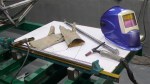
I need to be able to lift the engine into the chassis, but due to the lowered floor of the work area a standard engine lift won’t work. While I’m at it, it would be nice to be able to lift the entire assembled car off the build table, turn it ninety degrees, move it to the door, and roll it out of the shop. Below is the solution. Sorry there aren’t any plans. The build process was “go to your local metal recycling center, buy some scrap beams, clean them up, cut them as necessary, and weld them together”. I’m getting more comfortable with winging it in the machine shop.
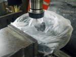
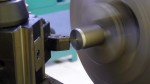
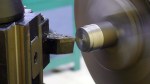
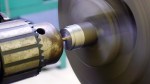
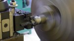
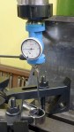
Also shown below is a mount I built to mount an angle grinder on the lathe. Parting-off has always been a problem. I’m just about to make the engine mounts, requiring at least 36 cutoff operations, and I figured I’d better solve the problem. I have a cutoff tool but only purchased a small number of carbide inserts; the inserts wear out really fast and I either have to order more from the US or drive at least an hour to a store that MIGHT have them. This baby works great, giving a clean straight cut. Just have to be careful not to let the abrasive get into the lathe.
-

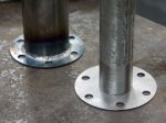
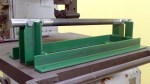
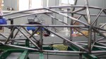
- Here’s what the overhead beam looked like when I started.
-

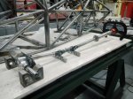
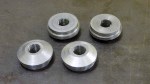
- Drilling holes to mount the wheels. Milling machine makes this easy.
-

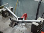
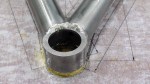
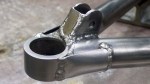
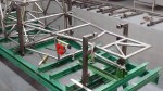
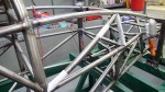
- Welding the uprights to the wheel supports
-

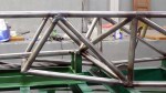
- Thick steel is so much easier to weld.
-

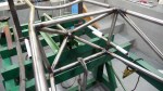
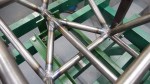
- Welding the uprights to the overhead beam, upside down. C-channel is temporary, so it doesn’t fall over.
-

- Finished. Trolley and chain hoist bought at Hardware House, Rayong.
-

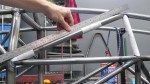
- So easy, even our spokesmodel can do it.
-

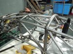
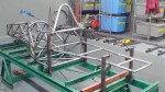
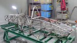
- Test lifting the chassis. Easy!
-

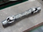
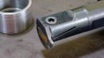
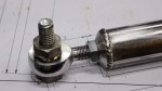
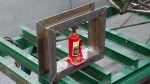
- Building adapter to lift the engine.
-
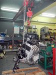
- First lift of the engine.
-
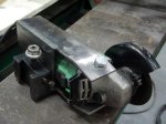
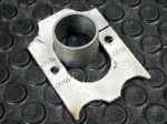
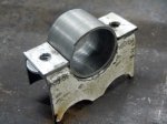
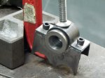
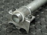
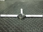
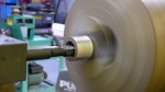
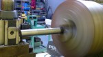
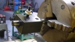
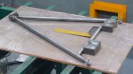
- While we’re building tools, here’s a holder to mount the angle grinder on the lathe.
-

- Parting off has always been a problem. Not anymore. Plastic is to keep abrasive off lathe.