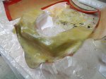
Two-part polyurethane foam expanding to fill the driver’s head surround.
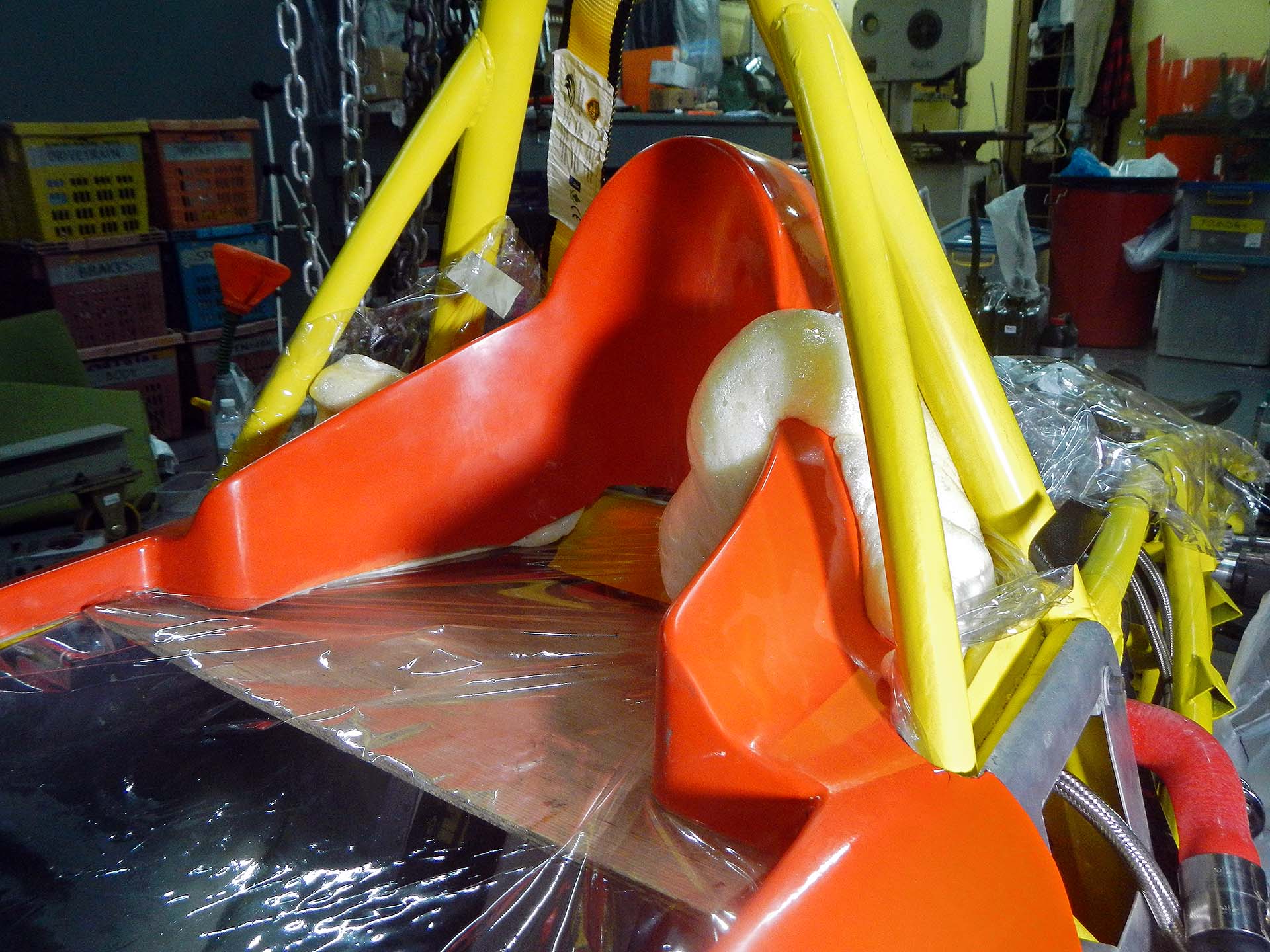
For proper protection in a crash, the driver’s head surround needs to be filled with foam. I placed an aluminum panel where I wanted the bottom of the foam to be, covered everything with plastic sheeting and poured two-part urethane foam into the cavity. The foam generates considerable pressure as it expands and cures, necessitating many iterations of trimming and fitting. I then sat in the car with the HANS device on, followed by many more iterations of trimming and fitting. Once the foam was cut to shape, I covered it in a single layer of fiberglass and epoxy, then painted it.
-
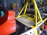
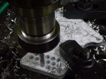
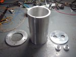
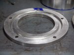
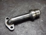
- Aluminum panel to set the bottom of the foam
-

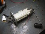
- Ready to fill with foam
-
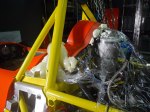
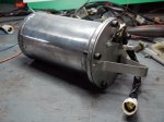
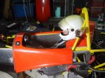
- Left rear view of expanding foam
-

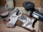
- Foam sanded and cut to shape
-
- Initial fiberglass covering
-
- Driver test fitting with HANS device
-
- Fiberglassing over the HANS device cutout
-

- HANS device cutout in driver’s head surround
-

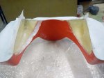
- Boffom view of finished head surround with cutout for HANS device