
So I was ready to build the suspension attachment points and decided I’d better do a finite -element analysis. It turns out they needed a lot of tweaking, and in a shin-bone’s-connected-to-the-thigh-bone kind of way, I ended up redesigning just about every suspension part all the way to the lug nuts. Part of this came when the quote on building the upper suspension attachment clevises came in way higher than expected, so I redesigned them so they could be laser-cut, hopefully much cheaper than CNC machining. Don’t have the new quote yet.
Also, I received the huge shipment of parts, supplies, and tools that I’ve been aggregating in LA for almost the past two years, and some idiot in purchasing (me) managed to order the wrong brake calipers. Everything was right except for the mounts, which are the lug style instead of the radial style. At least now I really know the tradeoffs between the two approaches. The upright for lug mount brake calipers is only about 35 grams heavier than the one for radials, and the calipers are $80 cheaper each. Over $1000/pound for that weight savings… Actually, that’s not quite fair as I don’t know the relative weights of the two caliper styles.
Anyway, we have lots of pictures of FEA meshes and results:
-

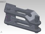
- FEA mesh for lower suspension clevis, attachment point for all four lower control arms
-

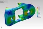
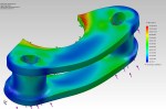
- Finite-element analysis results for lower suspension clevis
-
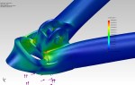
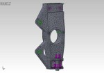
- FEA plot for front upper suspension attachment bracket that will be welded to the chassis.
-

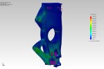
- FEA plot for one half of the laser-cut upper front suspension attachment clevis
-

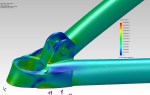
- FEA plot of one half of the upper rear suspension attachment bracket
-

- Detail of the FEA mesh for buckling analysis of left front lower A-Arm
-

- FEA buckling plot for left front lower A-Arm under braking load
-

- Detail of the FEA mesh for static analysis of left front lower A-Arm
-

- FEA plot of left front lower control arm under 1600 pounds braking force
-
- FEA plot for left front lower control arm under 1600 pound right-hand cornering load
-
- FEA plot of left front lower control arm under 1280-pound left-hand cornering load
-

- FEA mesh for front axle static cornering analysis
-
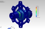
- FEA plot of front axle under cornering load
-

- FEA mesh for front axle static braking analysis
-

- FEA plot of front axle under braking load
-
- FEA mesh for front/rear steering arm
-

- FEA plot for front/rear steering arm under maximum cornering load
-

- FEA mesh for front upper control arm attachment bracket, to be welded to chassis
-
- FEA plot of front upper suspension attachment bracket
-
- FEA mesh for left front suspension upright static braking analysis
-
- FEA plot of left front suspension upright under braking load
-

- FEA mesh for left front suspension upright static cornering analysis
-

- FEA plot of left front suspension upright under maximum cornering load
-

- FEA mesh detail of left front suspension upright for snap-ring analysis
-

- FEA plot of left front suspension upright snap ring slot under cornering load
