Painting the Frame

Painted Frame

Painted frame, back in the lab

As you’ve probably figured out from looking at some of the photos below, I’ve painted the frame. I used Jotun Penguard 2-part epoxy right over bare metal after cleaning the metal with wire brushes and acetone. It took a few days as I had to let it cure before turning it, and all four sides had to be painted in turn in order to get every spot. No magic here, just lots of elbow grease.

Welding on More Random Jingly Bits

Shiny Frame

Some shiny frame porn for you…

I had not realized how many small brackets and things need to be fabricated and welded onto the frame before it can be painted. Weeks of work…

The nose mounts are so strong because the car will be lifted by a nose jack under the wing in the pits.


Redesigning Suspension Components

So I was ready to build the suspension attachment points and decided I’d better do a finite -element analysis. It turns out they needed a lot of tweaking, and in a shin-bone’s-connected-to-the-thigh-bone kind of way, I ended up redesigning just about every suspension part all the way to the lug nuts. Part of this came when the quote on building the upper suspension attachment clevises came in way higher than expected, so I redesigned them so they could be laser-cut, hopefully much cheaper than CNC machining. Don’t have the new quote yet.

Also, I received the huge shipment of parts, supplies, and tools that I’ve been aggregating in LA for almost the past two years, and some idiot in purchasing (me) managed to order the wrong brake calipers. Everything was right except for the mounts, which are the lug style instead of the radial style. At least now I really know the tradeoffs between the two approaches. The upright for lug mount brake calipers is only about 35 grams heavier than the one for radials, and the calipers are $80 cheaper each. Over $1000/pound for that weight savings… Actually, that’s not quite fair as I don’t know the relative weights of the two caliper styles.

Anyway, we have lots of pictures of FEA meshes and results:

Building the Cockpit

Time for a photo update showing how I built the cockpit, tube by tube.

Building the Chassis Nose

Starting Nose

Starting the nose tubes.

More Tubes

Test fitting the A, C, & D bulkhead side and bottom tubes.

Adjusting Jigs

Adjusting the jigs to fit as I go. Have to make sure they can be removed after welding.

Top Tubes

Test fitting the C to D bulkhead top tubes

Tube Rippling

Top tube: seam on inside of bend. Bottom tube: seam 45 degrees from inside of bend. Note slight rippling on upper tube. This is why seams must not be located on a major axis of bends.

Front Roll Hoop

Front roll hoop ready for welding.

Front Roll Hoop Done

Front roll hoop fully welded.

Better Weld

Welds are getting better. Now as long as I don't have to stand on my head I can make a pretty good weld.

Front Roll Hoop in Place

Front roll hoop in place. This required cutting the top tube frames. Not a problem as each piece will retain the correct shape.

Starting to Weld

A to C bulkheads welded. There is no B bulkhead (:-).

A, C, & D Bulkheads Welded

A to C to D bulkheads welded

Front Roll Hoop Welded

Front roll hoop welded, top diagonals added.

D-E Sides

D to E side diagonals added.

Nose Finished

The basic frame of the nose from the tip to the front roll hoop, finished.

Building the Front Keel

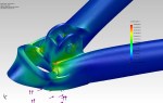
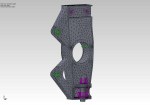
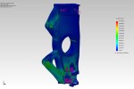
To get optimal suspension geometry and aerodynamics I’ve designed the car with a front keel under a raised nose. This gives the longest possible lower front A-arms, minimizing the angle changes of the front suspension as it goes through bump and jounce motions. The raised nose clear airflow around the front wing. My computational fluid dynamics (CFD) studies show airflow around the front wing is extremely important as the wing operates in ground effect and generates downforce all out of proportion to its size. I spent a considerable amount of time trying to increase the downforce generated by the underbody and rear wing to match that of the front wing, even though those elements are far larger.

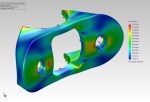
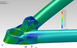
The front keel will use a stressed skin of aluminum formed to shape and riveted to tabs welded onto the frame tubes. This is the highest-stress area of the entire chassis, as under braking something like 2800 pounds of force will be transmitted through these members. You can visualize the car supported vertically on the front keel, with two more cars stacked on top of it, so this needs to be really strong.

Front Keel Tube

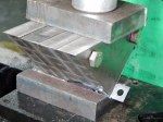
Front keel tube is drilled on the milling machine for front lower A-arm attachment points. This will give perfect mounting locations.

A-arm Attachments

Lower front A-arm attachment points were cut and drilled on the lathe, then tapped.

Welding Setup

Chassis table comes in handy again for welding the lower front A-arm attachment points into the front keel tube.

Finished keel tube

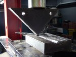
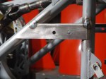
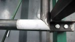
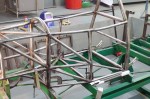
Completed front keel tube assembly. Front lower A-arm attachment points welded in place, ends of keel tube capped for strength.

Keel Tube in Place

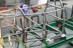
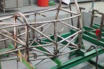
Front keel tube assembly rigidly located in place on chassis table.

Tube Bender Scrap

The 3-roller tube bender generates about 65 cm of scrap at each end on small-radius bends before it starts generating the correct constant -radius bend.

Keel down-tube

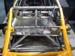
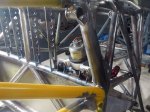
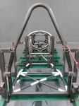
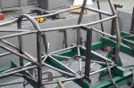
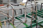
First front keel down-tube in place. The surface of the keel will be concave to let air flow better across the upper surface of the front wing, necessitating curved tubes to hold the keel.

More down-tubes

More front keel down-tubes. The two rear tubes are a recent addition to the design as this area needs to be phenomenally strong and the tubes weigh almost nothing.

Finished Front Keel

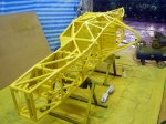
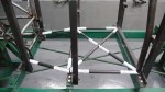
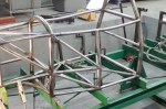
Finished front keel and front subframe

The Build Begins– The Front Subframe

After more than a year and a half of design and several months of tool preparation, that long-awaited day has finally arrived: the day I touch saw to metal on an actual car part. The first step is to build the front subframe that sell sit horizontally at the bottom of the nose of the car. The chassis table already has holes drilled and tapped for 3/8″ bolts locating the subframe members precisely. Here’s the first tube in place among the pins on the chassis table.

First Tube

First tube in place on the chassis table, bent to fit pins

First Weld

Lower front frame member cut to fit and tack welded in place

Finished Subframe

Finished front subframe, fully welded. Since it's laterally symmetrical, it's flipped over to weld the bottom.

Subframe on jigs

Front subframe raised to final position, supported by chassis jigs. Note Natural-Polymer Swing Press at right. A useful tool.