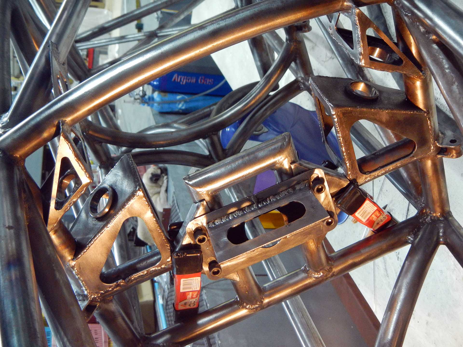
Finished differential, differential mounts, and rear sprocket
Thirty-four years ago I designed a car for the SAE collegiate Mini-Baja competition. The differential was inadequately supported in the middle, and although it didn’t break on us, it broke the next year and sidelined the car. I’ve felt guilty ever since, so that’s one mistake I’m determined not to repeat. This one should be adequate…
Later I plan on fabricating some sort of container or plugs to keep the oil in the diff.
-

- Left diff mount parts lathe turned, laser cut, bent
-

- Left diff mount ready for welding
-
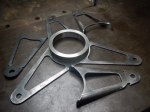
- Right diff mount parts
-

- Right diff mount ready for welding
-

- Welding diff mount. Aluminum insert reduces distortion
-

- Welding the second layer
-
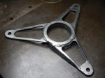
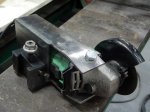
- Finished right differential mount
-

- Pressing differential bearing into mount
-

- Pressing the bearing & mount onto the differential
-

- Drilling lower right mounting hole. Washers align the drill bit.
-

- Lower right differential mounting bushing in place
-

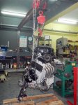
- Differential in place