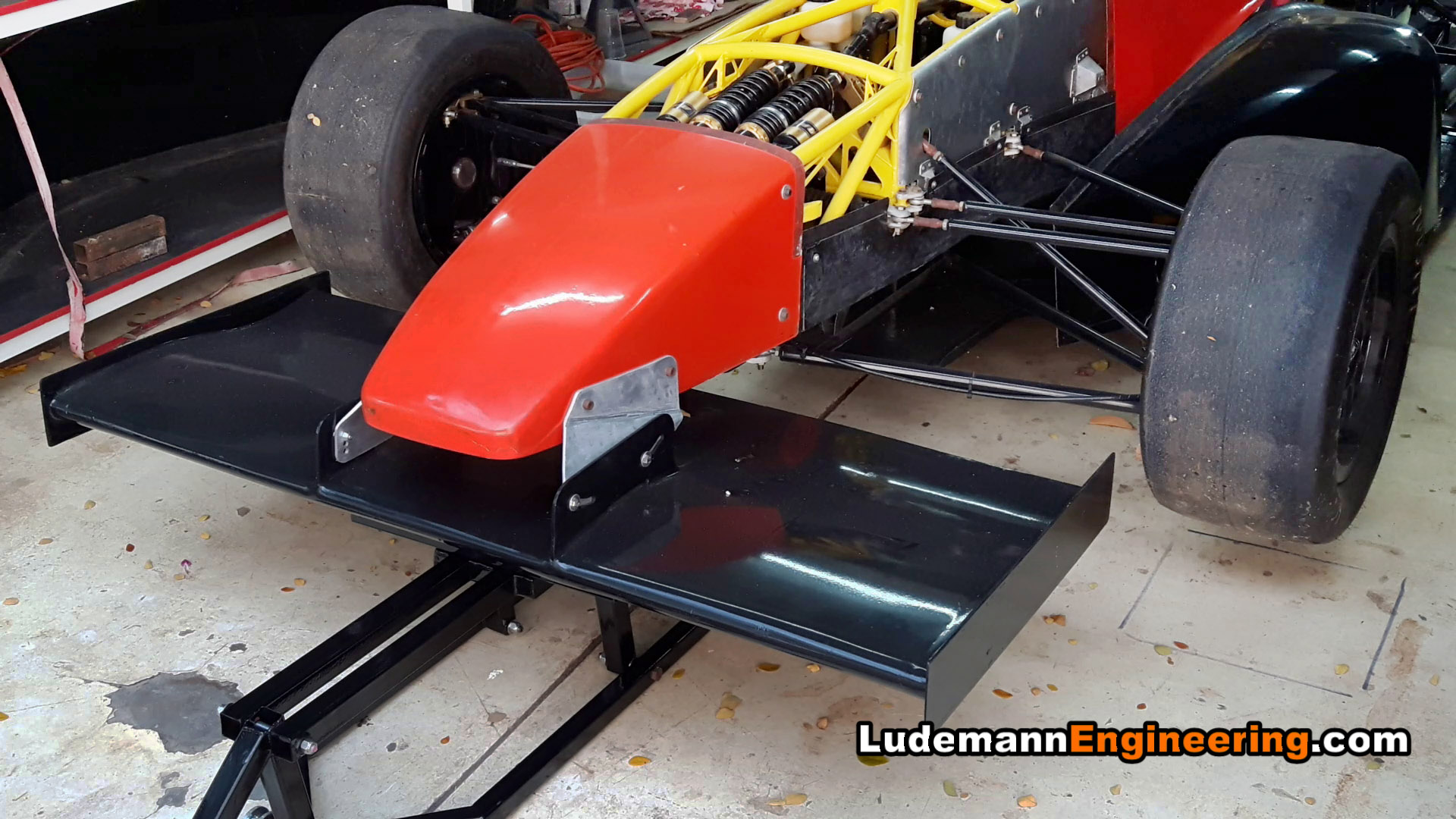
Finished front wing on the car (endplates to be added after setting ride height)
-

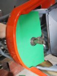
- Airfoil profile laser printed on sticker paper, stuck to aluminum sheet

-

- Airfoil profiles cut from aluminum sheet

-

- Homemade hot-wire foam cutter cutting airfoil section from styrofoam block

-

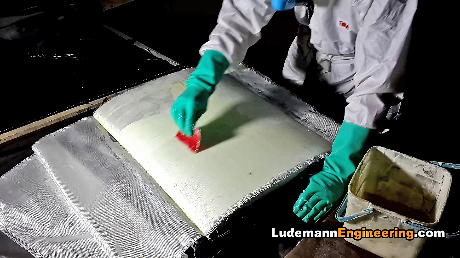
- Laminating outer skin of epoxy resin and fiberglass
-

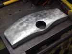
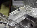
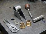
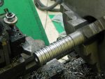
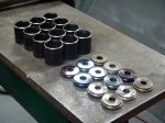
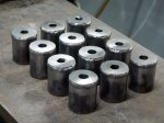
- Cutting aluminum jacking points to be laminated into the wing

-

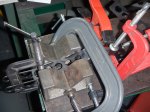
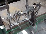
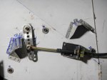
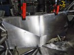
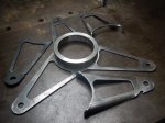
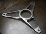
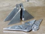
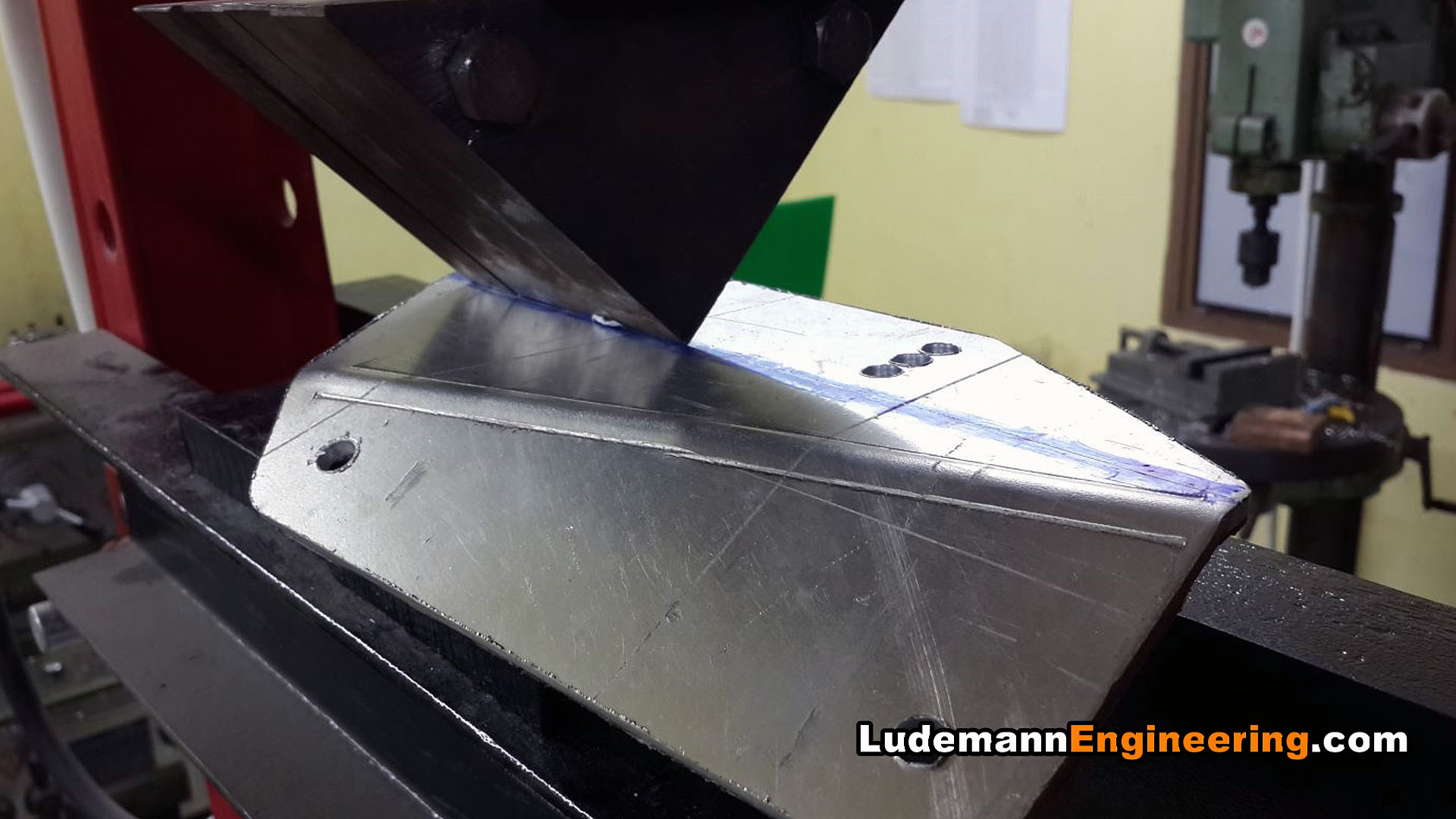
- Bending wing mounting brackets to be bolted to the nose
-

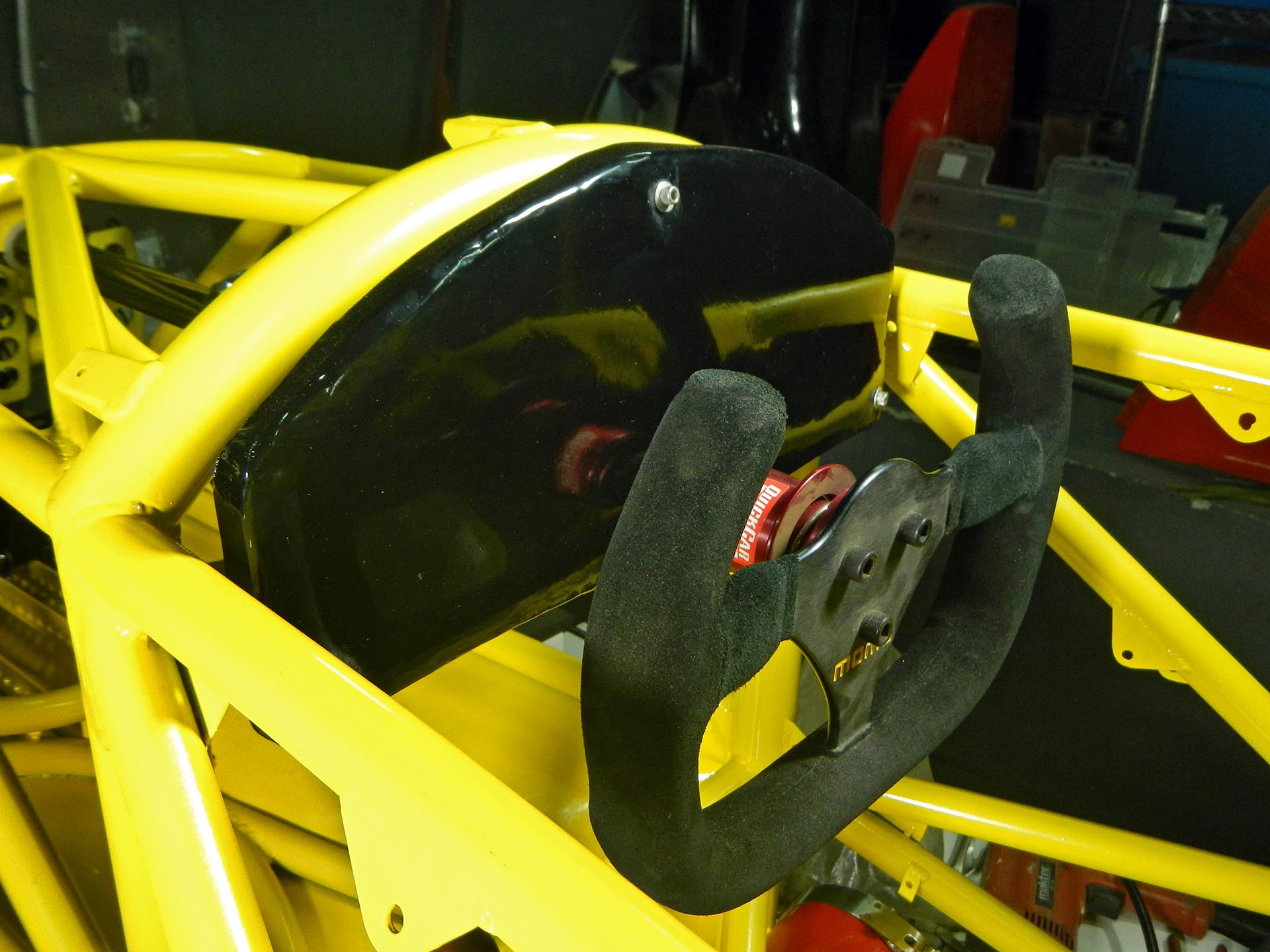
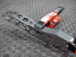
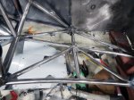
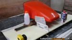
- Test fitting brackets on nose

-

- Test fitting, bottom view

-

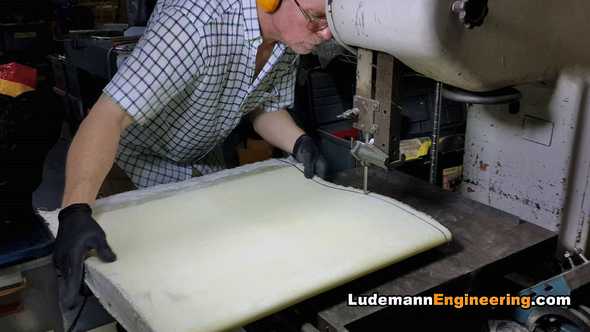
- Trimming front wing airfoil on the bandsaw
-
- Gluing 3 sections of front wing to brackets

-

- Reinforcing fiberglass skin across joints

-

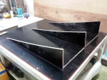
- Laminating end plates with honeycomb core

-

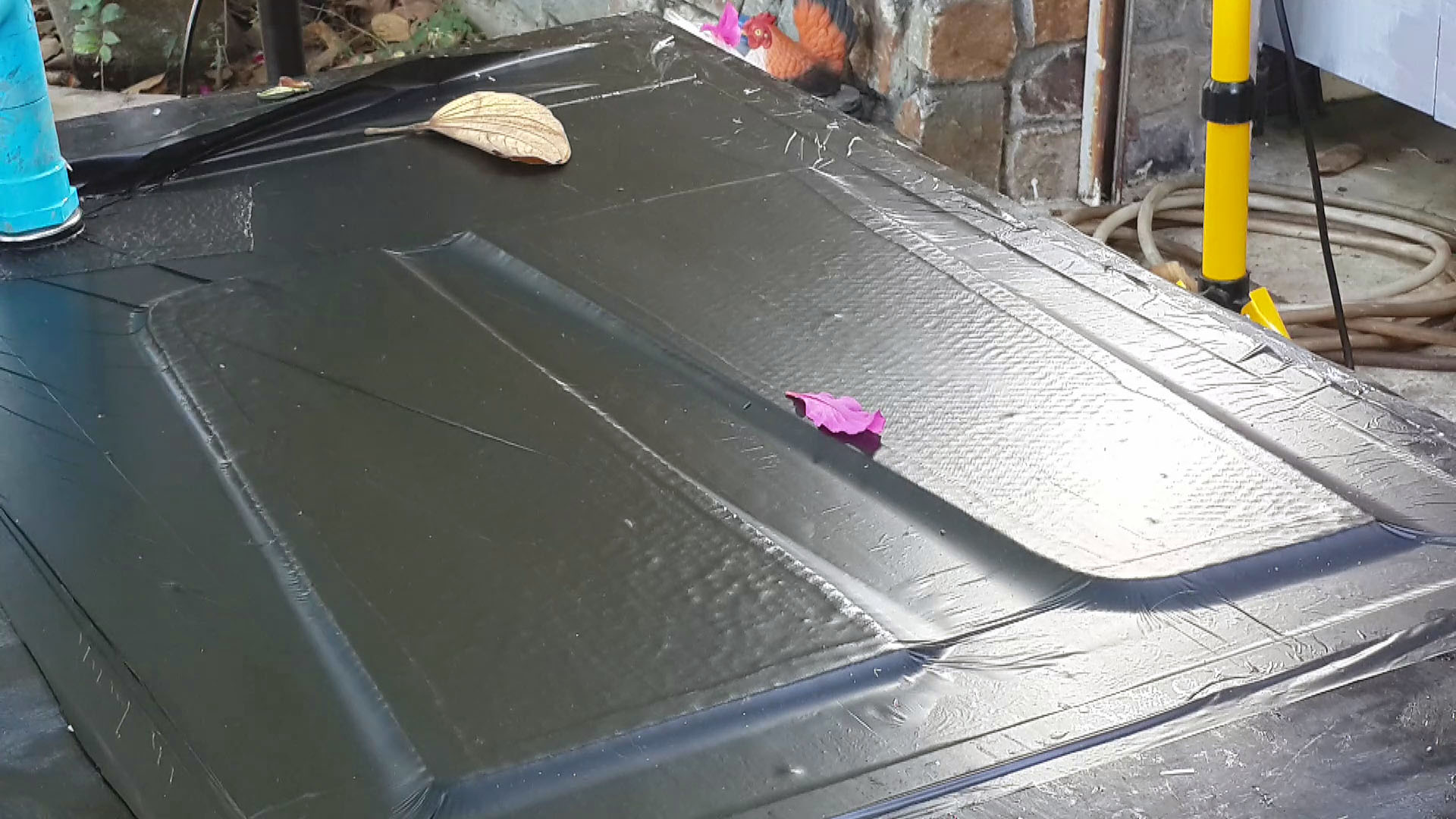
- End plates cure under vacuum
-

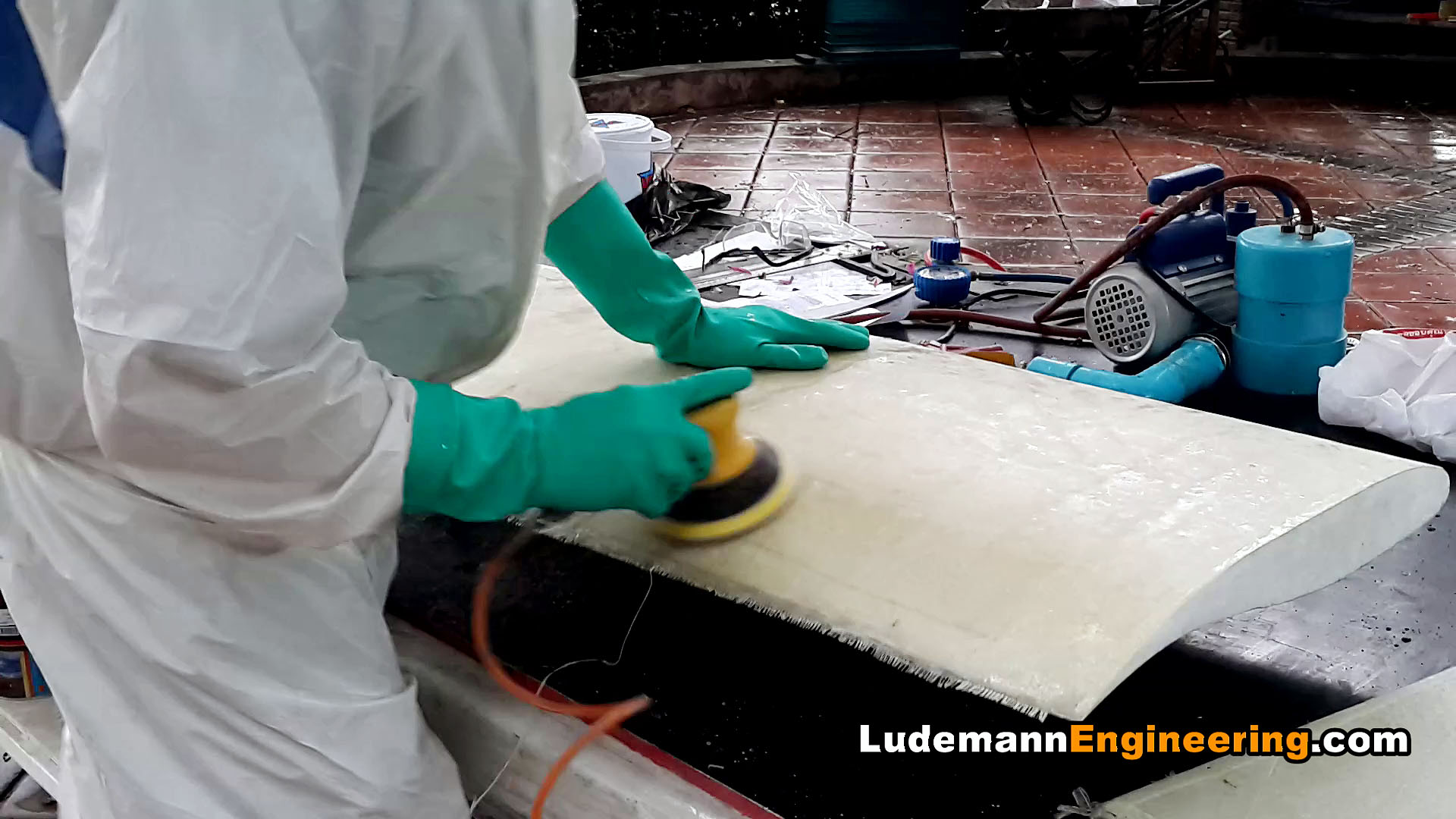
- Sanding with pneumatic double-action sander
-

- Laying up endplate mounting points

-
- Epoxy & microballoon filler to smooth out the spar

-

- Top coat of 2-part epoxy paint

-

- Car lifted by front wing