No, I haven’t just been sitting around the house eating chocolate, but a major malfunction in my main computer leaves me time to update the blog and get caught up on other things I should have done, like taxes. Unlike EVERY OTHER COUNTRY IN THE WORLD (except the Phillipines), even though I haven’t set foot in the USA in over four years, I still have to pay US taxes. The bright side is that California no longer considers me a resident so I don’t have to pay California taxes anymore, which is quite reasonable given that I moved out 11 years ago.
I made the mistake of turning the computer off overnight to help save the planet and all, and the next day it kept dying like someone pulled the plug. Computer shop says I need a new motherboard and graphics card, and oh, by the way, there are no new LGA 1366 motherboards for Intel i7 CPUs in Thailand and the old one will take about a month to fix under warranty. Which is understandable, given that Intel stopped making LGA 1366 i7 CPUs ages ago! Oh wait, they still make them? Or maybe not, from Intel’s website I can’t tell. At least Gigabyte’s warranty will cover their product, or maybe I just haven’t heard what their fine-print objection will be, yet. Azus, on the other hand, says my graphics card is corroded, and corrosion isn’t covered under warranty. Great plan! Make a product that corrodes, then say corrosion isn’t covered. It might be more honest to say “No Warranty”, though. The Azus graphics card was inside a warm computer (which was _almost_ never power-cycled) in an office environment for it’s entire life. Azus is now on my Deferred Vendor List.
Anyway, on to fabricating the lower A-arms, or control arms:

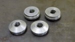
Repeat everything four times. Final result: four lower A-arms
-

-
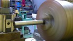
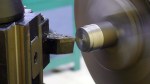
Starting with the spherical bearing cups, face and cut outside diameter
-
-
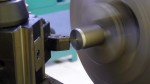
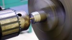
Cutting the internal diameter on a bearing cup. This is a press fit, so it has to be cut as perfectly as the tools will allow.
-
-
My boring bar won’t fit into my new quick-change tool holder, so I had to cut it down to fit.
-
-
Boring bar now fits into tool block.
-

-
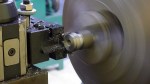
Cutting the groove for a snap ring. I wasn’t sure I could get the press fit perfect, so I included provisions for a snap ring
-

-
Snap ring in place for a trial fit.
-

-
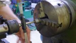
Using the cutoff tool to cut the part off the stock
-

-
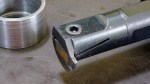
Bearing cup, spherical bearing, snap ring, and ID gauge for cup. I don’t have an internal micrometer, so used my external micrometer to cut a gauge to the precise length for the ID.
-
-
I ground a carbide cutting tool for the boring bar to the correct width to cut the snap ring groove. It took a lot of grinding. Carbide is really hard!
-
-
Starting the rod end receptacles that will be welded to the legs of the A-arms. Face and cut OD on lathe.
-
-
Cut step to fit inside A-arm tube.
-
-
Use center drill for accuracy.
-

-
Drill hole to be tapped for rod end
-
-
Using cutoff tool to part off
-
-
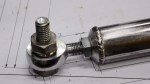
Tap for 3/8-24 left hand threads. A later version of the A-arms may have easy rod-end adjusters, so I’m using left hand threads here, too.
-

-
Cutting a chamfer on the face of the rod-end receptacle. Looks better, is lighter.
-
-
Four finished rod-end receptacles
-
-
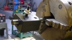
Setup for tack welding rod end receptacle into A-arm tube
-

-
Tack welded in place
-

-
Welded all the way around. Holding the tube in a V block makes it easy to turn while welding
-

-
Made 2 aluminum bushings to fit inside the bearing cup and locate it on the jig
-
-
Rod ends are held in jig for welding.
-

-
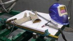
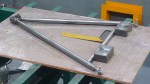
A-arm jig is made from printed drawing glued to plywood.
-

-
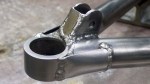
Spherical bearing cup fully welded to one leg of an A-arm
-
-
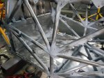
Both legs of an A-arm fully welded to a bearing cup
-

-
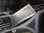
A-arm bearing cup braces marked and cut
-

-
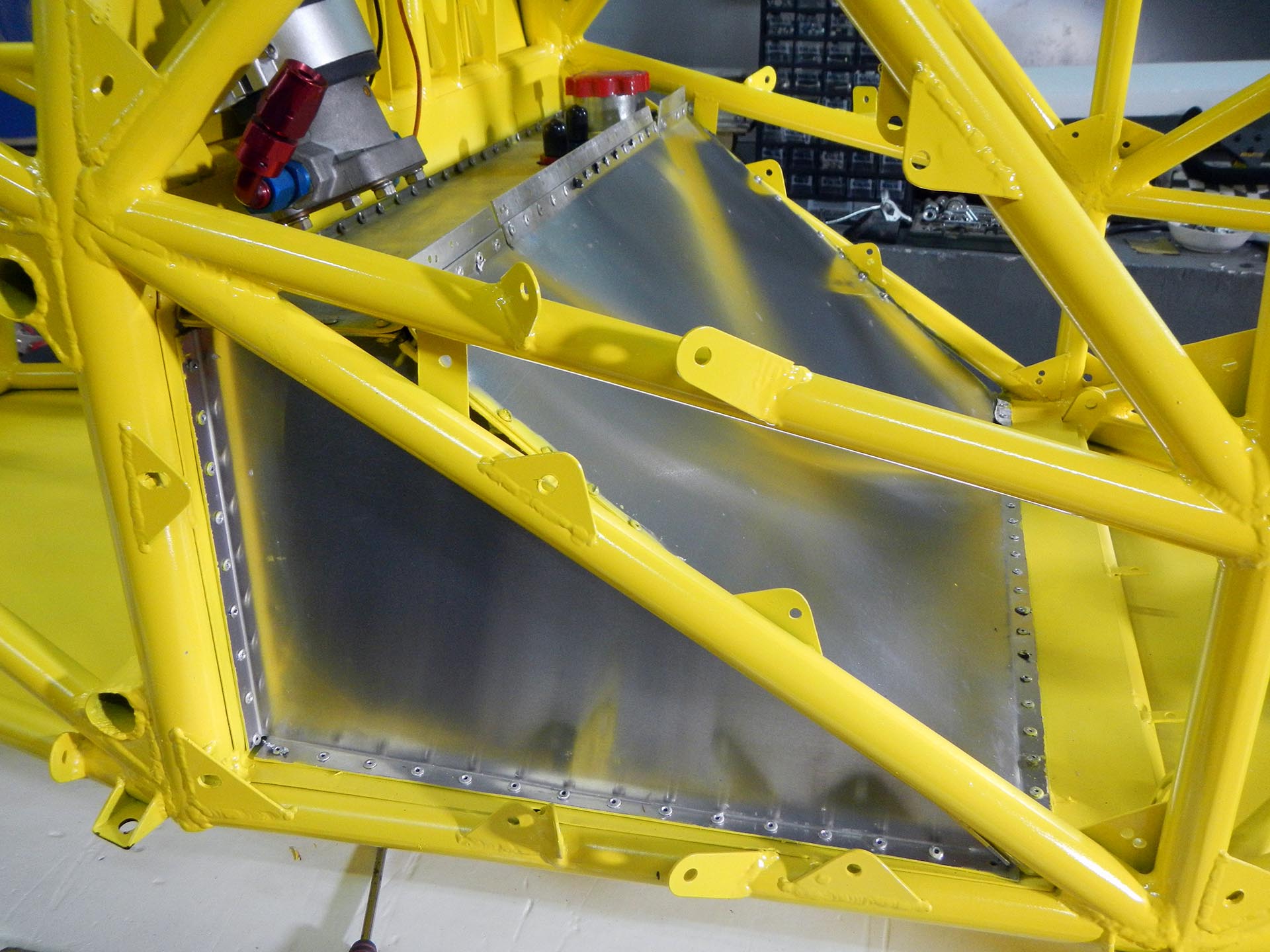
Bearing cup braces in place and welded
-
-
Pushrod mount in place and welded. These pieces were made with the patented (not patented!) technique of printing on sticker paper, cutting with a plasma cutter, grinding to exact shape.
-

-
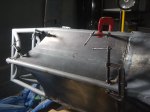
Spherical bearing is pressed into place on my home made hydraulic press. Custom bushings were made to only push on the correct places, like not the ball.
-
-
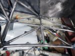
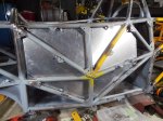
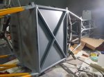
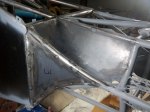
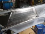
Anti-intrusion bar test fitted
-

-
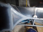
Anti-intrusion bar fully welded. Weld shrinkage is a problem here.
-
-
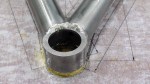
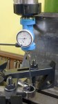
Welding distorted the bearing cap enough that I had to recut the bore. First, find the center of the hole.
-

-
Next, use a boring head to cut the hole to exact dimension. Very tricky; had to use 1/2 the smallest tick mark on the boring head. Total overlap for press fit is around 0.001″
-

-
Repeat everything four times. Final result: four lower A-arms