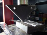
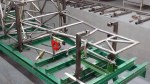
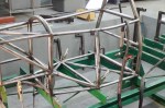
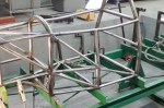
A mysterious form begins to take shape on the slab
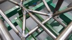
Now it’s time to test one of the big unknowns of this project: can the top rails be formed in the shape of a complex 3D spline, and can the left and right sides be made to match? The CAD software won’t even allow a structural member in the shape of a spline, requiring them to be composed of straight sections and arc sections. Other exoskeleton cars have been built, but as far as I know always with a single curve in the main frame members. And of course a tubing bender is designed with the assumption that it will be used to form constant-radius segments. I believe this is the first car to be done this way, so I’ve put a lot of effort into the chassis jigs to get it right. The top rail spline is a key to the beauty of this design. To make a long story short, it is in fact possible to bend a 3D spline on a tubing bender. It just takes a lot of trial and error, patience, and about a day of work per rail. And luckily, overbending can be corrected by running the tube back through the bender, clocked 180 degrees.
“The pricking of my thumbs” is not entirely rhetorical. In fact I almost cut off my left thumb while building the top rails, so a word about safety. A tubing bender is a SERIOUS PIECE OF EQUIPMENT. It won’t even notice bones and flesh being fed into its’ rollers. I had already turned off the bender and reached to grab the tube as it was twisting on the way into the bender. The bender caught my glove and started pulling my thumb in, stopping at the last possible millisecond before inflicting permanent damage. It hurt and left a mark, but I was insanely lucky. So, 1.) Never wear gloves while using a tube bender. They protect you about as much as Saran Wrap, and it’s better to have your fleshy appendages dangling about unprotected to remind you of the danger. 2.) NEVER, NEVER touch the tube on the side being fed into the bender. Always handle the side being fed out. and 3.) Before pushing the “on” switch, stop, think, and say to yourself “I’m not going to become an amputee on this bend.”

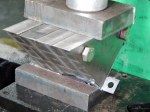
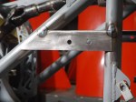
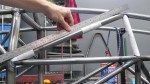
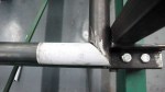
So here's the problem: how do we make this straight tube fit all those notches located in 3D?

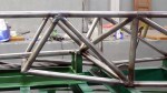
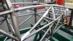
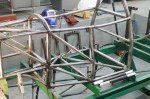
Left top frame rail about half done

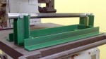
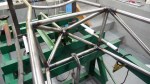
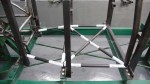
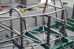
Top left frame tube fitted to chassis jigs

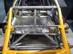
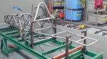
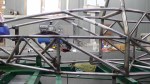
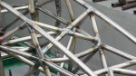
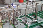
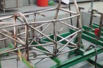
Both top frame tubes bent to shape and matched to each other, in place on the chassis jigs. Now it's possible to get a feel for the size and shape of the car. It's really going to be beautiful!

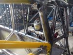
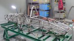
The main frame rail, running from the front to the back of the car, is so light I can lift it with a single finger.

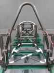
Sitting inside the chassis for the first time. Time to make vroom vroom noises.