
Here’s what we’re building, sort of. Rather than build a CAD model of an actual assembly of stringer and rib parts, I extruded cuts into the solid model so that the slots will appear in the correct places when I make cross-section drawings at the appropriate locations. This is actually harder to visualize than you might think. I wasn’t sure it would go together flawlessly, especially since the cuts in both the ribs and stringers went to two different depths depending on the typical height of each region. I didn’t want long floppy sticking up from the cuts:
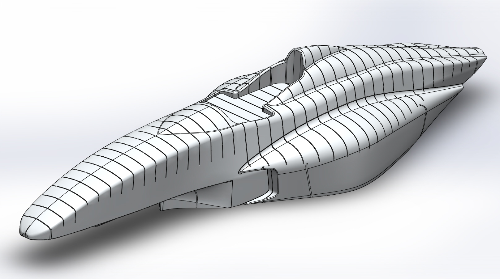
Original 3D CAD model showing slots for assembling plywood ribs and stringers.
-

- Longitudinal stringer drawings printed on A0 paper and pieced together
-
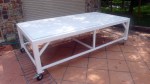
- First we need a table to build it on…
-

- All cross sections cut from 3mm plywood and assembled on the table. THANKS DAVE!
-

- Starting the process of filling in the voids, using wadded newspaper topped with two-part foam
-

- Foam filling continues…
-

- Cut to shape with hacksaw blade, belt sander, and sandpaper
-

- And continues…
-

- And continues…
-

- etc.
-

- Filling and trimming as I go.
-

- Many applications left voids, which I attempted to fill with more foam.
-

- Using whatever is convenient to constrain the foam. Here, bungee cords hold old pillows.
-

- And continues…
-

- This foam was difficult to work with. No reaction for 30 sec., then hard in 20 more sec.
-

- Foaming is finished.
-

- Filling some voids.
-
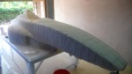
- Trimming almost finished.
-

- Just the driver’s head fairing left to trim.
