I ended up applying ten coats of SikaFloor epoxy to try to build a hard base for further finishing. Even this gave me problems, though, as it appears that the two-part urethane foam continues to expand indefinitely. Every time I would finish a section, next time I looked at it, it needed more work. For a long time I just thought my eyes were getting more demanding, but I finally realized the body buck was slowly changing shape, bulging out between the ribs. Once I figured this out, I just tried to finish the molds as fast as possible. I also installed air conditioning in this part of the workshop, and kept it running at night to avoid temperature-cycling the pattern.
If you’re thinking of doing this yourself, a better way to do it would be to just fiberglass straight over the plywood forms, using tape or something to support the first layer of fiberglass while curing. About a 3mm fiberglass shell should do it. Then use body putty right over that, using standard auto-body finishing techniques. That way there’s no foam between the ribs to push outward and mess up the shape. The only time you need foam is when you’re really sculpting something, like the sidepod air intakes. Oh, by the way, plan on about 1,000 hours of work.
After the floor epoxy there were several rounds of primering, puttying and sanding, followed by two coats of black two-part epoxy paint. This was sanded with 400, 800, 1200, and 2000 grit wet-or-dry sandpaper, then machine-polished with rubbing compound. The top layer was 9 coats of “Hi Temp Mold Release”, applied by hand strictly according to the instructions.
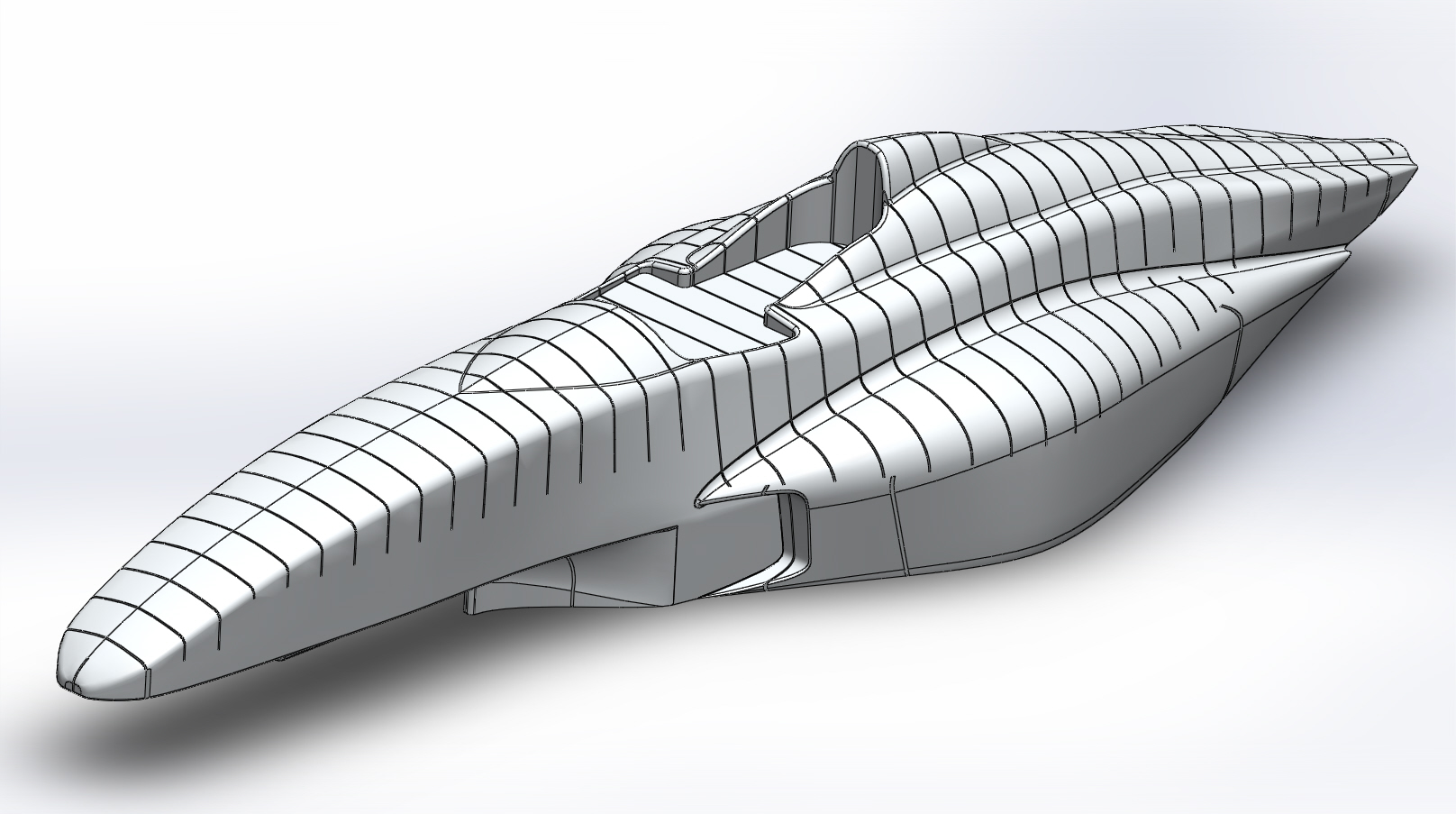
When I started to think about how to split up the body panels, I realized that the “horse collar” head surround would be impossible to remove when the car was finished, as it would interfere with the main roll hoop. This necessitated going all the way back to the SCCA rule book, where I took another look at the minimum cockpit opening specifications. I found that I could meet the minimum cockpit opening size with a fixed head surround, but I had to cut the “arms” off it. So, you get to see that surgery in the photos below.
-

- Many coats of floor epoxy, some puttying in between
-

- More coats…
-

- More coats…
-

- Almost done…
-

- Finally, ten coats of floor epoxy applied
-

- Now primer…
-

- Sanded down…
-

- Putty applied…
-

- Sanded down…
-

- More primer…
-

- Sprayed on some dark gloss paint to check the reflection
-

- Sanded down again
-

- More primer, and a guide coat
-

- Sanded down again
-

- Ready for top coats
-

- First coat of black two-part epoxy
-

- First top coat, another view
-

- Sanded down…
-

- Second epoxy top coat
-

- Oops, won’t be able to remove the driver’s head surround from the finished car.
-

- Cut off the arms of the head surround
-

- Body putty
-

- Primer
-

- Voila…
-

- Perfect. Driver’s head surround is now fixed in place.
-

- Machine polished but not yet waxed
-

- Nine coats of mold release wax
-

- Purty…
-

- Mmmmm, shiny…