
-

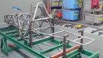
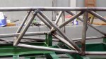
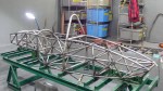
- Removed the chassis from the jigs for the first time. Welded the bottoms of all the joints, which brought the chassis back to true & flat
-

- It’s a commuter car! You can carry it like a briefcase.
-

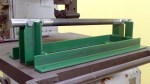
- Test fitting the rear beltline tubes. Chassis table has pins to locate these tubes, too.
-

- Rear subframe beltline welded…
-
- And into place.
-

- First parts back from the machinists’. Rear keel jig and the keel itself. Beautiful and accurate! Thanks, Somkuan!
-

- Rear keel, ready for welding.
-

- …and welded.
-

- Welded rear keel jig. Really starting to get the hang of this welding stuff. Yay!
-

- Bottom perimeter of the engine compartment fabbed and welded.
-
- Finished rear keel and rear keel jig.
-
- Engine compartment left side lower tubes
-

- Engine compartment right lower diagonal
-

- Bulkhead H right vertical lower tube
-

- Another example of how my Solidworks fishmouthed tubes fit, this one at the front end of the rear keel.
-

- Lower diagonal tubes holding the front of the rear keel.
-
- H-J inner upper diagonal tubes securing the front of the rear keel.
-

- H-J bottom perimeter tubes in place. These 3 tubes were welded flat on the table then lifted into place. Here you see the bottom of the car start to curve upward to clear the diffuser.
-

- H-J side diagonals. Here we work our way from front to back to avoid cutting off the ends of the tubes to fit them in from the side.
-
- J left and right lower verticals
-

- J to L left and right lower diagonals
-

- Released from the chassis table again to weld the bottom of all the joints. It’s so much easier this way I don’t even try to weld upside-down anymore.
-
- J-K inner bottom diagonals hold the rear of the rear keel
-

- K-L diagonals secure the rear of the rear keel to the beltline. This is the back end of the frame.
-

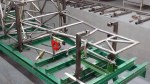
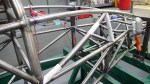
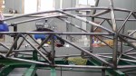
- Top frame rails from the main roll hoop to the back of the car are finally in place. Now we can see the complete outline of the frame.
-
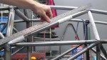
- G-H upper diagonals are curved outwards to allow us to remove the engine from the top. The curve must be in the correct plane.
-
- From this angle you can see the curve. Removing the engine from the top is a design change based on feedback from the ApexSpeed.com forum. Top rail will be made removable later.
-

- H bulkhead, upper left vertical. Note that it’s not really vertical, but leans forward and inward.
-

- Test fitting the G-J upper diagonals. Sometimes it’s necessary to fit a bunch of tubes before welding any in place.
-
- Now we start welding them in place from front to rear. These are the G-H upper diagonals.
-

- H, H-J, J upper tubes (6). Skipped a couple of photos…
-
- It’s almost done. Just a few inner diagonals left.
-

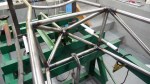
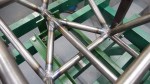
- J bulkhead, inner diagonal UL-LR. This area of the frame is extremely strong as it has to support the suspension rockers and engine mounts.
-
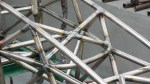
- J bulkhead inner diagonals, LL-UR, 2 pieces
-

- H-J inner diagonals support the rear engine mounts.

Great work!
A really amazing manufacturing.
I have never seen a car using the central keel at the rear axle too.
Just out of my curiosity, what will be the final chassis weight?
And how you would like to place rockers and dampers?
Yes, the central keel was never possible on a car with a longitudinal engine and transmission. My front and rear suspensions are nearly identical, with the goal of perfectly neutral handling at the limit. In a perfect corner the front wheels would point straight ahead, and I’ll be steering with the throttle.
Current chassis weight is 86 pounds without the forward roll hoop braces. Springs and dampers both front and rear are ahead of axle centerlines. So far there are no photos of this on my site, but it’s all designed.
-Jim