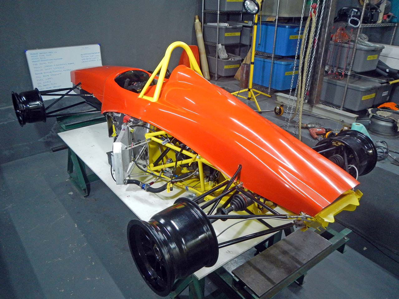
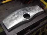
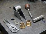
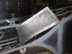
Low-profile bike-engined car or motorcycle-engine car billet aluminum oil pan installed on a 2007-2008 K7 Suzuki GSX-R1000 engine
When building a motorcycle-engine car, the oil pan has to be replaced with a flat-bottomed pan. This allows the engine to sit flat on the floor pan of the car, lowering the center of gravity. Also, the g-forces experienced by a car engine are completely different from those seen by a motorcycle engine. When a motorcycle corners the forces are still straight down through the centerline of the engine, whereas when a car corners the force pushes the oil to the side of the engine. Through sad experience this was found to make the engines explode. A proper flat-bottomed oil pan has a separate compartment for the oil pickup, connected to the rest of the pan by one-way flappy doors that keep the oil near the pickup during cornering and braking. Note that some flat-bottomed oil pans are made for stunt motorcycle riding and so use a swiveling oil pickup. The car-racing guys don’t have enough experience with these, so don’t use them. Your engine may explode, and this would be bad.
As it seems no one on the Internet has ever explained how to install such an oil pan before, so here it is. My oil pan arrived without even a word of explanation, yet the operation detailed here is fairly important. As in, your engine is toast if you try to start it without doing this. Now that the Thai government has prohibited importation of all used motorcycle parts, my engine is now completely irreplaceable. So that would be bad.
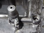
2006 and earlier GSX-R1000 models had the oil pressure relief valve sandwiched between the engine block and the oil pan. In 2007 Suzuki moved the valve to a new housing closer to the center of the oil pan, connected by a passageway to the original location. In the original location they replaced the valve with a simple cylindrical connector gizmo with o-rings at each end so that oil would still flow to the new valve location. This gizmo is popped out by hand and discarded, and the oil pressure relief valve is flipped top for bottom and inserted in its place. This should become clearer in the photos below.
As I’d really like it if my engine didn’t leak, I’ve used Permatex gasket sealant on all sealing surfaces and around the heads of the oil pan mounting bolts. The original oil pan used special gasket washers under the mounting bolts that had fallen by the wayside at some time in the past, leaving my engine with just two out of fourteen. Since I couldn’t find these anywhere on the Internet outside of a complete engine-rebuild gasket set, I sourced 6mm copper crush washers in their place along with new 6mm x 40mm socket head cap screws as the original ones won’t work with the new oil pan. Has to be socket-head cap screws; hex head bolts will just sit on the outside of the oil pan as their head won’t fit into the counterbores in the oil pan. Needless to say, all this required many trips to the hardware store and much Internet research. You’re welcome.
UPDATE: A tip of the hat to the guys on ApexSpeed.com, in particular Gary Hickman of Edge Engineering, who jumped right in with all the know-how and history to figure out what’s going on here. You can see (and buy) the latest version of these oil pans here: EdgeCNC.com .
-

-
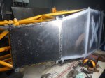
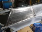
Stock oil pan, left, with billet oil pan, right.
-
-
Detail of the stock oil bypass relief valve housing, bolted to oil pan
-
-
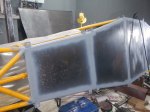
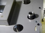
The corresponding location on the billet oil pan. Hmmm, no oil pressure relief valve?
-

-
Stock pan oil pressure relief valve housing removed.
-

-
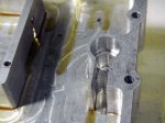
Underneath you find the actual oil pressure relief valve.
-

-
Pull it out by hand and it looks like this.
-

-
Flip it 180 degrees, end for end, and it fits into the billet oil pan like this.
-

-
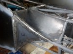
Overview of the oil pan area on the bottom of the engine.
-

-
Detail of the connector gizmo.
-

-
The connector gizmo pops out easily by hand.
-

-
Oil pressure relief valve goes in here like this.
-
-
Oil pressure relief valve in place.
-

-
Gasket sealant on the oil pan flange.
-

-
Oil pan bolts, 6mm x 40mm, copper crush washers, gasket sealant.
-

-
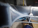
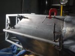
Oil pan baffle in place, gasket sealant on top, too. Ready to install.