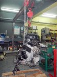
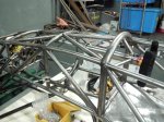
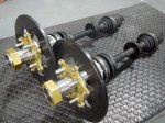
Rear suspension, axles and differential in place
The car will use standard Honda Civic axle halfshafts, and I had the choice of cutting, sleeving and re-welding them, or building extenders that effectively widen the differential to meet the unmodified halfshafts. The cut/sleeve/re-weld option would eliminate the axle hardening and leave unknown strength, and I’ve since seen an example where this was done and the axle broke right at the weld. The option of “widening” the differential has several advantages. First, we can easily replace the halfshafts if necessary in the future with off-the-shelf parts. Second, moving the inner constant-velocity joint closer to the plane of the control-arm pickup points minimizes the plunge, or change in length, required as the suspension moves through its travel. Third, the halfshafts become equal length, eliminating torque steer. Now you may say “but, the extensions will be of different length and will twist unevenly so the torque steer won’t be eliminated”. The extensions will be much stiffer than the axle shafts so that won’t be the case.
So the choice was clear. We started with a differential and a couple of halfshafts as raw material…
-

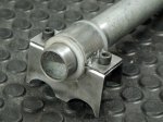
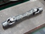
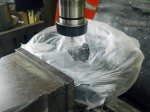
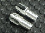
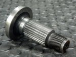
- Inner CV joint, inner piece as raw material
-

- Cut off the part we don’t need
-
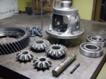
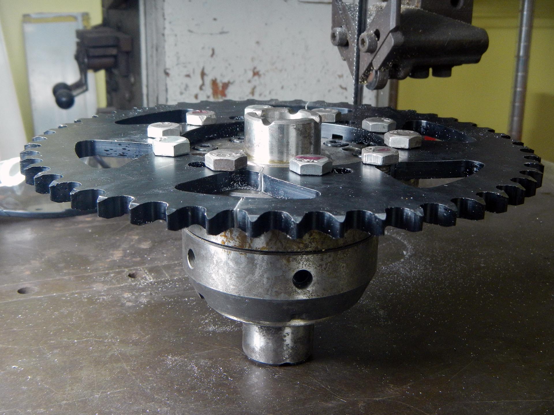
- Disassembled donor differential
-

- Grinding a diff spider gear
-
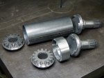
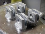
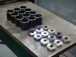
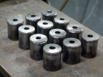
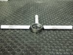
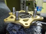
- Finished parts
-

- They fit together like this
-

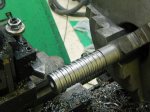
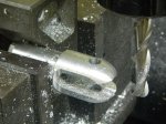
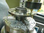
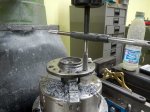
- Welding on the lathe to ensure linearity
-
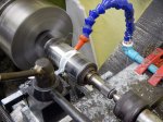
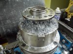
- Cleaning up on the lathe after welding
-

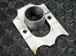
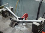
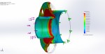
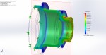
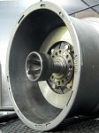
- Starting the outer extension support
-
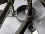
- Preparing to weld the outer support
-

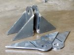
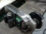
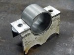
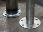
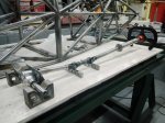
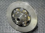
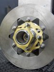
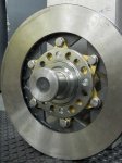
- Finished outer extension support
-
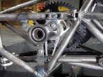
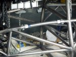
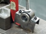
- Finished support installed