I’m getting some interest in the car from here in Thailand, but they want it SOON. So I’ve had to step up the rate of progress, even though it hasn’t showed here on the blog. Instead, I’ve been designing and designing and designing… It’s a big step from an assembly design that seems pretty much correct, to a set of drawings and IGES or DXF files that you’re willing to pay real money to fabricate. Everything has to be checked, from the load cases used in the finite element analysis to the hole clearances for every bolt.
For example, did you know that a 1/4″ bolt doesn’t go into a 1/4″ hole? The proper size of the hole is 0.257″ for a close fit or 0.266″ for a free fit. Of course, then you have to take into account the width, or kerf, of the laser beam used to cut the metal, which can be 0.01″ or 0.25mm but varies with the type of material and thickness being cut, and the laser beam is actually a cone that can be focused on the top, middle, or bottom surface of the piece. Many parts had to be redesigned for the materials and processes I’ve been able to locate in Thailand. Here it’s not a simple matter of looking up all the local suppliers on Google and giving one a call. Thailand has a great number of very small companies that rarely have websites, and even if they exist they’re mostly in Thai, which as a special favor to web search engines uses no spaces between words. Yes, you read that right. Using no spaces would be OK if there were only one way to parse a stream of Thai characters, but haha, you make joke, eh? And then if I can actually get someone on the phone, I have to communicate in Thai. Like that’ll work.
Last year I was looking for a foundry to cast aluminum uprights, and I found one (using Startpage, not Google) less than an hour from here. Their website had a Google map and everything! So I drive there, and I’m within 100 feet or so, asking motorcycle taxi drivers where the company is. No idea; there’s never been a foundry around there. I show them the address and they say oh, that’s way over on the other side of town. The person answering the phone number has no idea what I’m talking about. I give up.
On the other hand, recently one of those Google ads that look like the first links on your search actually showed me something that I needed and couldn’t find with a search: a small local company that fabricates custom radiators. So I managed to find their shop this week and got a quote for the radiator. Quote comes by email entirely in Thai. Google translate does a pitiful job of translating Thai, but I caught on the email wasn’t spam. Fantastic price, by the way. Cheaper than what I paid for a used race car radiator on EBay. I decided I didn’t really like how that one would fit, so I designed one that’s ideal for my application and figured I’d worry about fabrication later. Problem solved, yay!
The Thai racers who are interested in the project have emphasized that the price is crucial, which means more redesign. Surprisingly for me, this is the same thing I’ve heard from the people in Singapore who’ve contacted me. Sometimes it’s easy to dash off a quick machined aluminum design, but it takes a lot more thinking to do it with laser-cut steel pieces. The equivalent in steel typically ends up being a little heavier, but that’s an example of why Formula 1000 has a minimum weight rule. Laser-cut steel hand-welded into a complex component is just about free in Thailand.
Where before I was planning on making just about everything in my machine shop, now I’m looking at fabricating as much as possible at subcontractors. Luckily a friend found a large CNC machine shop not too far from here, and the guy running it speaks English and understands drawings and computer files and tolerances and clearances and everything. I’ve now received my first batch of CNC machined parts from them and they look great. Combined with the first batch of laser-cut parts and a few parts I’ll fabricate and modify myself, I now have everything to make the car a roller.
Anyway, on to today’s gallery:
-

-
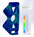
Front upright FEA mesh
-
-
Front upright FEA cornering & braking load
-

-
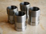
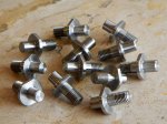
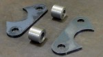
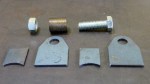
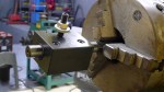
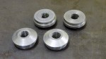
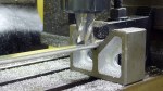
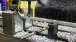
Right upright CNC’d part
-

-
Front suspension rocker arm FEA mesh
-

-
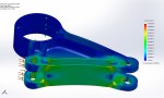
Front suspension rocker arm FEA results
-

-
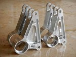
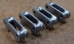
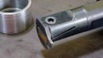
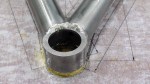
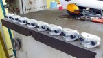
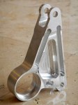
Front suspension rocker arm CNC machined part
-

-
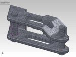
Rear suspension rocker arm FEA mesh
-
-
Rear suspension rocker arm FEA results
-
-
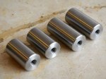
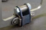
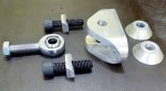
Rear suspension rocker arm CNC part
-
-
Left steering arm FEA mesh
-

-
Left steering arm FEA results
-

-
Left steering arm CNC part
-

-
Stub axle FEA mesh
-

-
Stub axle FEA results
-
-
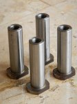
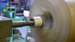
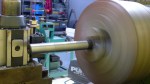
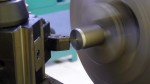
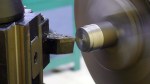
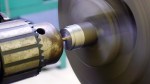
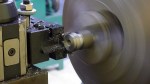
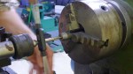
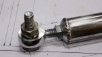
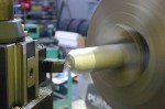
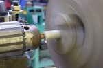
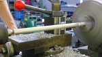
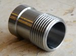
Stub axle CNC part, chrome-moly steel