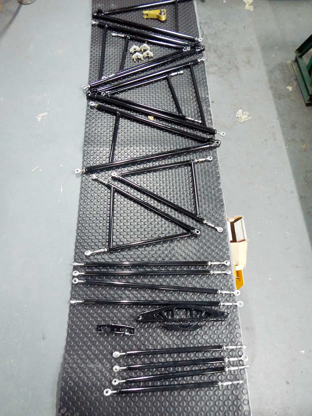
Finished set of control arms, tierods & pushrods
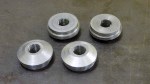
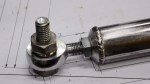
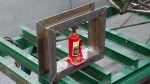
The upper control arms are all identical except that the bearing cups are mirrored from the left to the right so that the snap rings are on the bottom. If I can find a way to stake the spherical bearings then all four could be identical. Staking is a process that uses a hydraulic press to deform the bearing cup into a chamfer around the circumference of the spherical bearing, holding it permanently in place.
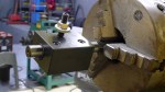
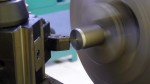
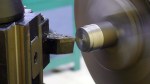
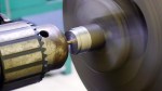
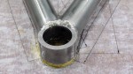
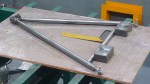
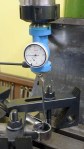
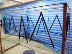
I printed out the layout of both control arms onto size A0 paper, glued the paper to a sheet of plywood, and drilled holes for the centerlines of each rod end and spherical bearing. This gives me a jig I can use for tack welding the parts in place. Washers under the bearing cups locate them vertically for tacking. The bearing cups proved a little too thin to weld without distortion, so I had to re-cut the spherical bearing bores after welding. Luckily I have an indexable end mill of just the right diameter, and running my mill at high speed with a lot of coolant gave a good finish on the bores. I then pressed the spherical bearings into place before painting as I wanted to make sure there were no glitches that would require messing up the paint to fix.
I sprayed Jotun Penguard 2-part epoxy paint directly onto the steel after first making sure the steel was scrupulously clean with a Scotchbrite pad on an angle grinder, followed by a cleaning with acetone and paper towels. The finish came out beautifully.
-

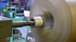
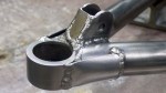
- Upper A-arm first leg
-

- Upper A-arm second leg
-

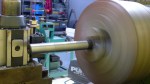
- Upper A-arm anti-intrusion bar
-

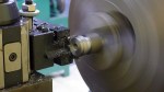
- Re-cutting the spherical bearing bores
-
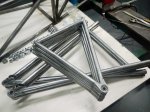
- Finished set of 8 A-arms
-

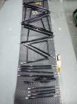
- Finished set of eight pushrods & tierods
-

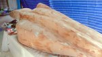
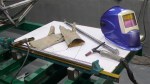
- Ready for paint
-
- Gloss black
-
- Finished set of control arms, tierods & pushrods