Aluminum side impact panels finished and mounted
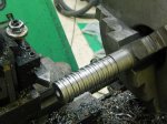
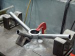
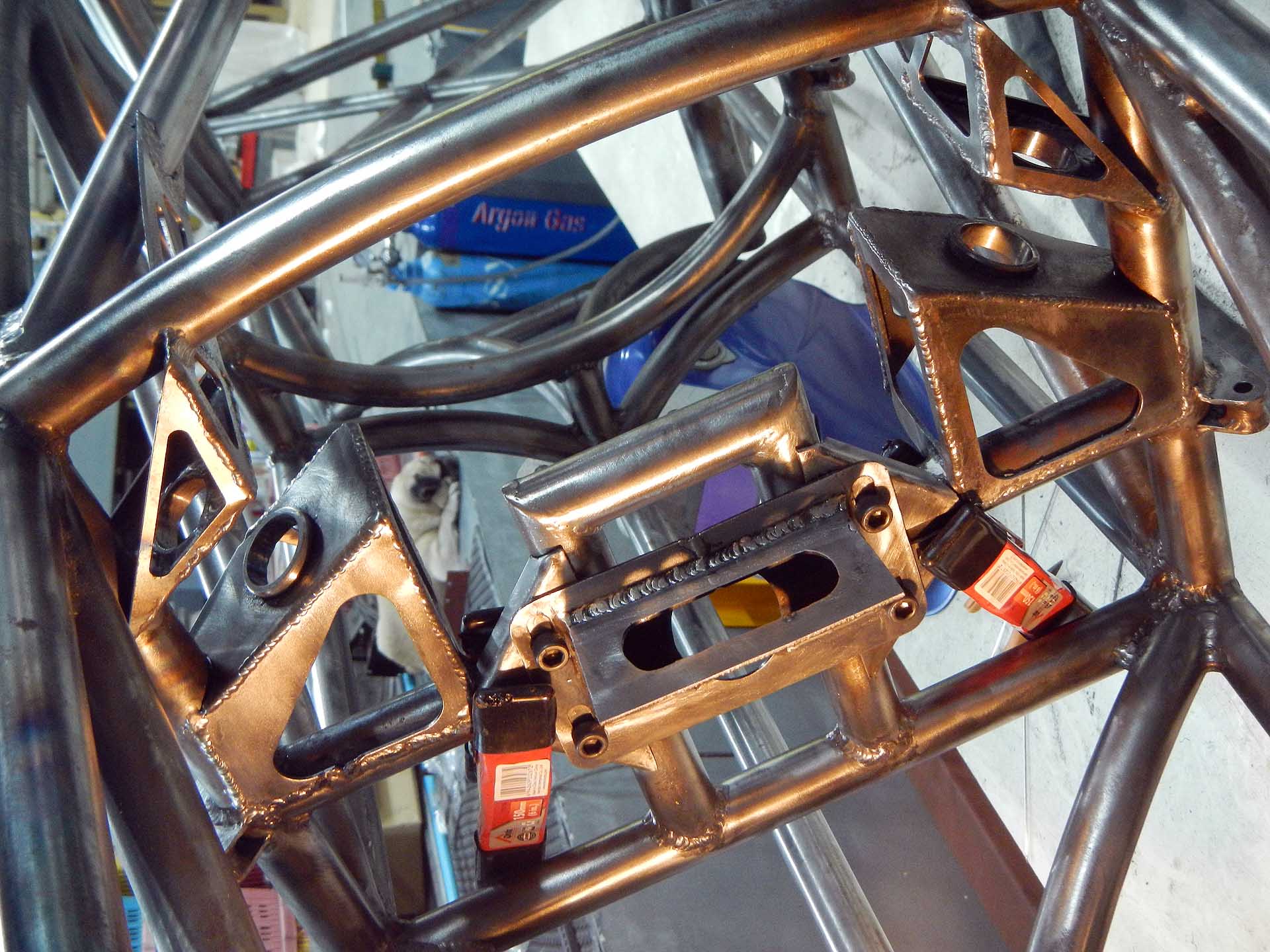
SCCA Formula 1000 rules require side-impact protection consisting of either kevlar laminated to the inside of the body, or 0.060″ aluminum or 18-gauge steel bolted to the frame. To keep the side impact panels from being used as a stressed member, attachment points to the frame must be more than 6″ apart. Mine are laser cut from 1.6 mm aluminum. The mounting holes were also cut by the laser to be sure of the 6″ rule, but this was a mistake as it made the mounting tabs much harder to fabricate. It would have been much easier to weld the tabs in place with holes already drilled, then drill through the tabs to the aluminum panels for exactly aligned holes. As you can see from one of the photos below, the panels fit perfectly. This project was a lot of cutting and welding with little apparent progress.
-

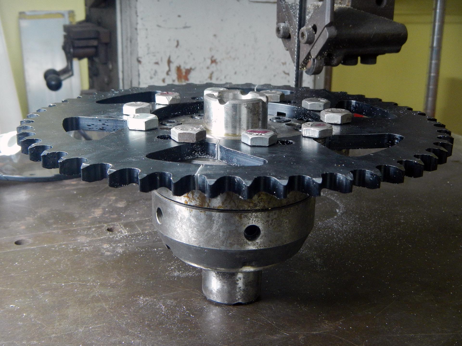
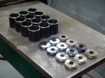
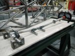
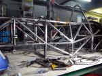
- Cutting several mounting tabs at once
-

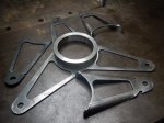
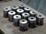
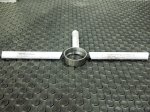
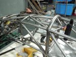
- Left side tabs laid out and ready to weld
-

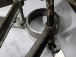
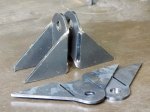
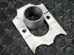
- A simple jig to hold tabs in the right plane for welding
-

- Amazing fit of the laser cut panels
-
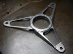
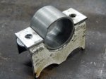
- Left side tabs done
-
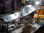
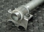
- Right panel. Note how panel was rolled over frame tubes.