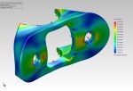
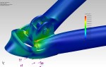
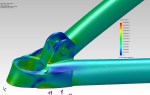
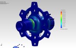
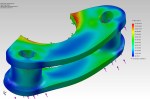
Lower suspension attachment clevis assembly drawing
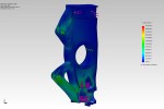
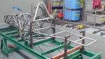
It seems that other people who’ve built cars from scratch attempt to get their cars rolling on the ground as soon as possible, so I figure I’ll do it that way too. With that in mind, it’s time to start fabricating the suspension. First up: lower suspension attachment clevises. I ordered 7075 aircraft aluminum from the United States as part of my big shipment. It’s amazing stuff– stronger than steel but light as aluminum. These assemblies have to be extremely strong, as I calculate that under braking the front one takes a load of over 4400 pounds.
-

- Start with a solid chunk of 7075 aircraft aluminum, here scribed for cutting slightly oversize
-

- Blanks are cut to size with thinnest abrasive cutting blade in high-speed angle grinder. I tried using a 12″ cutoff saw, but it couldn’t cut this high-strength aluminum.
-

- Finished raw blank
-

- Facing both sides of the blank with carbide-insert face cutter end mill
-

- Milling holes for bolts to attach to chassis. PDF drawing printed on sticky paper at 1:1 eases the layout and provides a useful double-check against errors.
-

- Milling the first outside radius on the rotary table.
-

- Milling the second outside radius
-

- 45-degree faces are rough cut with the angle grinder, then clevises are supported on V-blocks clamped to the milling machine.
-

- 45-degree faces milled smooth with face cutter
-

- Repeat eight times. Ready for slot milling.
-

- Milling the slots for the rod ends using a ball-end mill.
-

- Milling holes for the rod-end retaining bolts
-

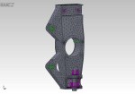
- Milling an additional relief for the rod ends. Test assembly showed interference, so I went back to the computer model and, sure enough, there it was. Now I know to use the interference and clearance detection tools.
-

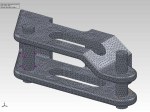
- Finished lower A-arm clevises. Outside radius on front was also cut on the rotary table / milling machine.
-

- Lower suspension attachment clevis assembly drawing