Building the Body Buck: Part 2, Putty, Prime, Repeat

Sikafloor

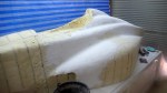
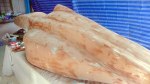
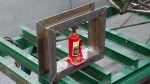
After the first coat of ultra-hard Sikafloor epoxy

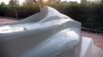
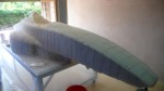
Here’s where the heavy lifting begins. Many, many passes of plaster or putty, sanding, and primer. The first step was to coat the entire body in plaster, which is best done the messy way: just plunge your hand into the bucket of plaster and smear it on the body buck. Plaster is much better for filling voids than foam is. Especially the insulation foam that comes in a can. Don’t, under any circumstances, use the canned spray foam. It remains flexible permanently, and keeps slowly expanding over a period of weeks or months. If you use it, as I did, to fill voids, you’ll spend days and days digging it out wherever it reaches the surface, refilling the holes with auto body filler.

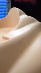
I discovered that spackling compound, made for smoothing house walls before painting, works great after the plaster. Plaster has a short working time, and you end up mixing lots of little batches when you’re filling ripples. The spackling compound goes on smoothly, you can work it just about as long as you want, it sands extremely easily, and it sands to a feather edge. I also tried gypsum, but it has the disadvantage of remaining water soluble as it doesn’t cure.

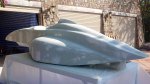
I put on a gallon of Jotun Penguard 2-part enamel filler, then found the only auto-body paint supply shop in town and discovered “sprayable body putty”, so I followed up with a couple of gallons of that, spackling and sanding between coats. About the third coat of sprayable body putty, I noticed that the body buck was swelling badly where it had been in the sun. Uh-oh. It turns out the foam expands and contracts with temperature. After that I kept the car only in the garage, never letting sun touch it. It took 2-3 weeks to fix that mistake, now using auto body filler and a double-action (DA) air-powered sander with 40 grit sandpaper, a great combination for this work.

So when I finally got that mess cleared up, I wasn’t too keen on spraying another coat of primer and potentially distorting the surface again. Instead, I went straight to an extra-hard epoxy used for floors, called Sikafloor. This is a very unusual paint as it’s intended to be used only on horizontal surfaces, where it remains liquid for a long time as it flows to become perfectly flat. I sprayed it on, almost unthinned, an “off label use”, but it worked great for my purposes.

Building the Body Buck: Part 1, Ribs & Foam

Here’s what we’re building, sort of. Rather than build a CAD model of an actual assembly of stringer and rib parts, I extruded cuts into the solid model so that the slots will appear in the correct places when I make cross-section drawings at the appropriate locations. This is actually harder to visualize than you might think. I wasn’t sure it would go together flawlessly, especially since the cuts in both the ribs and stringers went to two different depths depending on the typical height of each region. I didn’t want long floppy sticking up from the cuts:

Body Buck CAD

Original 3D CAD model showing slots for assembling plywood ribs and stringers.

Fabricating the Suspension Attachment Points

Hot Off the (3D) Press: Suspension Upright 3-D Print

The suspension uprights have gone through a long evolution, but I’m zeroing in on the goal.

First Design: Machined Billet Aluminum

This design uses radial-style brake caliper mounting. Needed to be redesigned when someone ordered the lug-mount calipers and had them delivered all the way from the USA. Probably a Freudian slip as they’re less expensive.

Machined Upright

Second Design: Fabricated Steel

Fabricated Upright

Second design was fabricated from steel. Unfortunately, welding will eliminate the temper in the heat-affected zones. The weakening due to this is hard to predict, and can only be eliminated by heat treatment. That would mean days or weeks finding and learning to deal with a heat-treatment supplier.

Mesh Quality

Mesh used for finite-element analysis of fabricated steel upright.

Upright FEA

Finite-element analysis stress plot for fabricated upright. Strong enough, but where are those heat-affected zones?


Third Design: Cast Aluminum

Here’s the final result of literally hundreds of design revisions, ensuring that the upright is strong enough and as light as possible. This design is made possible by the new technology of 3d printing, which will be used to make the master “plug”, from which molds will be made to cast the actual part. Note that the steering arm is not an integral part of the upright, but is modeled together with the upright because the FEA runs much faster this way.

FEA mesh plot for cast upright

FEA stress plot inner

Cast Upright FEA

View from outside

Finally, the Master Copy

The upright had to be split into four pieces for 3D printing; split vertically so I can make two mold halves and remove the masters from the molds, and split horizontally to fit the 3D printer. The 3D printer extrudes hot ABS plastic in X-Y layers onto a heated Z-axis stage with 0.3mm resolution. The print is slightly rough and the parting plane is slightly warped, which will have to be corrected with auto body putty, primer, sanding, and paint. The cast aluminum blank will still require several machining steps to cut off the gate and sprue, drill mounting holes, bore the bearing hole and retaining ring slot, and mill the brake caliper mounts. Still far better than trying to machine individual parts (or even a mold pattern) this complex, which would be approximately impossible and semi-infinitely expensive.

Beautiful, huh?

One half printed in two colors to highlight the split required to fit it into the 3d printer

Set of 4

Full set of four 3d prints. The cylinder protruding in the upper left is the gate, where molten aluminum will be poured into the finished mold.

Top View

Some people get excited by shoe sales. I get excited by this!


Fabricating the Lower A-arms

No, I haven’t just been sitting around the house eating chocolate, but a major malfunction in my main computer leaves me time to update the blog and get caught up on other things I should have done, like taxes. Unlike EVERY OTHER COUNTRY IN THE WORLD (except the Phillipines), even though I haven’t set foot in the USA in over four years, I still have to pay US taxes. The bright side is that California no longer considers me a resident so I don’t have to pay California taxes anymore, which is quite reasonable given that I moved out 11 years ago.

I made the mistake of turning the computer off overnight to help save the planet and all, and the next day it kept dying like someone pulled the plug. Computer shop says I need a new motherboard and graphics card, and oh, by the way, there are no new LGA 1366 motherboards for Intel i7 CPUs in Thailand and the old one will take about a month to fix under warranty. Which is understandable, given that Intel stopped making LGA 1366 i7 CPUs ages ago! Oh wait, they still make them? Or maybe not, from Intel’s website I can’t tell. At least Gigabyte’s warranty will cover their product, or maybe I just haven’t heard what their fine-print objection will be, yet. Azus, on the other hand, says my graphics card is corroded, and corrosion isn’t covered under warranty. Great plan! Make a product that corrodes, then say corrosion isn’t covered. It might be more honest to say “No Warranty”, though. The Azus graphics card was inside a warm computer (which was _almost_ never power-cycled) in an office environment for it’s entire life.  Azus is now on my Deferred Vendor List.

Anyway, on to fabricating the lower A-arms, or control arms:

Class Photo

Repeat everything four times. Final result: four lower A-arms

Building a Simple Hydraulic Press

I’ll be needing a press to insert the spherical bearings into the control arms and to insert the wheel bearings into the suspension uprights, so I took a couple of hours and built a simple hydraulic press. It’s just a strong steel frame that will give a small 5-ton hydraulic car jack something to push against. It’s taller than it is wide to be able to press items of different sizes by turning the frame on its’ side. Regarding painting, I’m finding that, with modern paints, I don’t need to use primer. I just clean the metal with a wire brush on a variable-speed angle grinder, clean it again with acetone and paper towels, then spray the topcoat on directly. This gives a thin, hard coat that sticks well.

Fabricating Lower Suspension Clevis Spacers & Washers

Need some spacers to keep the clevises from interfering with some of the frame tubes. Also, custom load-spreading washers that my FEA says are important:

Making Chips… Finally!

Assembly Drawing

Lower suspension attachment clevis assembly drawing

It seems that other people who’ve built cars from scratch attempt to get their cars rolling on the ground as soon as possible, so I figure I’ll do it that way too. With that in mind, it’s time to start fabricating the suspension. First up: lower suspension attachment clevises. I ordered 7075 aircraft aluminum from the United States as part of my big shipment. It’s amazing stuff– stronger than steel but light as aluminum. These assemblies have to be extremely strong, as I calculate that under braking the front one takes a load of over 4400 pounds.

Modifying the Lathe Quick-Change Toolpost

So I imported this quick-change tool post for my lathe, which appears to be some kind of standard, but a standard that my lathe just doesn’t happen to abide by. I needed a large (~1 1/2″) hole in the bottom of this solid tool-steel block. I tried drilling it with a carbide-insert drill, but after several minutes had made a cut so shallow it could only be felt by dragging a fingernail across it. After watching a few Youtube videos, though, I decided it must be possible and came up with the setup below, a solid carbide end mill slowly enlarging the hole on a rotary table. The mill left an amazingly high-quality finish.

Contents: 1 Race Car Kit, some assy. req’d

I’ve been accumulating parts for almost the past two years in a warehouse in Los Angeles as it’s easier to buy things in the US and ship them all the way to Thailand than it is to just buy them in Thailand. Also, I only wanted to navigate Thai customs one time. Finally gave them the go-ahead to ship, and a few weeks later everything arrived at my door. Includes just about everything that I can’t make myself or buy in Thailand: wheels, brake calipers, brake discs, brake pads, master cylinders, Aeroquip tubing and fittings, torsen differential, rear axles, spherical bearings, bearings, rod ends, 2007 Suzuki GSX-R1000 engine, crash padding, radiator, oil cooler, kevlar, vacuum-bagging materials, vacuum pump, Halon fire system, and more. Also, everything I need to fully fit out my machine shop, like a rotary table, angle table, and cutting tools. Better than Christmas!

Some assembly required. May require common household items such as tape, scissors, stapler, lathe, milling machine, and TIG welder.