
I finally found a video that conveys the full speed available from a Formula 1000 race car, a Gloria F1000 doing a hillclimb in Italy (skip forward to 3:15). THIS is why I’m building a race car:
Tag Archives: formula 1000

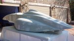
Fiberglass Mold Layup, Parts 4, 5, 6…
Probably the main thing to explain here is how I create the overlaps in the molds. The edge of a mold is marked on the body buck with duct tape, which will leave an impression in the mold for later trimming of the finished part. Then after removing the mold from the buck, I lay in a strip of 1″ duct tape touching the existing tape, then another strip touching that one. I then remove the first two strips of tape, leaving the edge for the next mold with a 1″ overlap.
-

- Left sidepod waxed 10 times and marked
-

- After first layup
-

- After second layup
-

- Right sidepod mold released
-

- Body buck prepared for engine cover layup
-

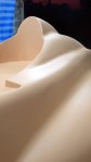
- Engine cover gelcoated
-

- Rolling out the bubbles
-

- Catalyzed polyester resin. Color change after stirring vigorously for 1 min.
-

- Brushing resin onto fiberglass mat
-

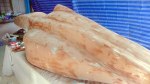
- Engine cover layup finished. Molds are about 6mm thick.
-

- Released engine cover mold
-

- Body buck after mold release
-

- Tape detail showing how overlaps in molds are created
-

- Leg cover gelcoated
-

- Leg cover fiberglassed
-

- Cockpit gelcoated
-

- Laying out plastic template for cutting fiberglass
-

- Template is used to precut fiberglass mat
-

- Resing & catalyst are pre-measured in usable quantities
-

- Cockpit fiberglass layup finished
-

- Cockpit mold released
-

- Body buck after release
First CNC Parts, Class Photos

Suspension uprights, two left, two right
-
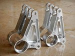
- Suspension rocker arms, 2 front, 2 rear
-

- Suspension steering arms, 2 left, 2 right
-

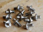
- Wheel lug nuts
-
- Stub axles CNC’d from billet chrome-moly steel
-

- Wheel drive pins CNC’d from chrome-moly steel
-
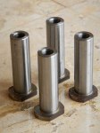
- Upright lower spherical joint pins
-

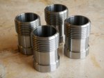
- Upright lower spherical joint pin bushings
-
- Suspension rocker arm shafts, 2 front, 2 rear. Chrome-moly steel
-

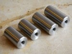
- Suspension rocker arm shaft bushings
-

- More suspension rocker arm shaft bushings
-

- Upright upper spherical bearing bushings
-
- Brake disc mounting pins
Getting caught up on my blogging…
Shiny Happy CNC Parts
I’m getting some interest in the car from here in Thailand, but they want it SOON. So I’ve had to step up the rate of progress, even though it hasn’t showed here on the blog. Instead, I’ve been designing and designing and designing… It’s a big step from an assembly design that seems pretty much correct, to a set of drawings and IGES or DXF files that you’re willing to pay real money to fabricate. Everything has to be checked, from the load cases used in the finite element analysis to the hole clearances for every bolt.
For example, did you know that a 1/4″ bolt doesn’t go into a 1/4″ hole? The proper size of the hole is 0.257″ for a close fit or 0.266″ for a free fit. Of course, then you have to take into account the width, or kerf, of the laser beam used to cut the metal, which can be 0.01″ or 0.25mm but varies with the type of material and thickness being cut, and the laser beam is actually a cone that can be focused on the top, middle, or bottom surface of the piece. Many parts had to be redesigned for the materials and processes I’ve been able to locate in Thailand. Here it’s not a simple matter of looking up all the local suppliers on Google and giving one a call. Thailand has a great number of very small companies that rarely have websites, and even if they exist they’re mostly in Thai, which as a special favor to web search engines uses no spaces between words. Yes, you read that right. Using no spaces would be OK if there were only one way to parse a stream of Thai characters, but haha, you make joke, eh? And then if I can actually get someone on the phone, I have to communicate in Thai. Like that’ll work.
Last year I was looking for a foundry to cast aluminum uprights, and I found one (using Startpage, not Google) less than an hour from here. Their website had a Google map and everything! So I drive there, and I’m within 100 feet or so, asking motorcycle taxi drivers where the company is. No idea; there’s never been a foundry around there. I show them the address and they say oh, that’s way over on the other side of town. The person answering the phone number has no idea what I’m talking about. I give up.
On the other hand, recently one of those Google ads that look like the first links on your search actually showed me something that I needed and couldn’t find with a search: a small local company that fabricates custom radiators. So I managed to find their shop this week and got a quote for the radiator. Quote comes by email entirely in Thai. Google translate does a pitiful job of translating Thai, but I caught on the email wasn’t spam. Fantastic price, by the way. Cheaper than what I paid for a used race car radiator on EBay. I decided I didn’t really like how that one would fit, so I designed one that’s ideal for my application and figured I’d worry about fabrication later. Problem solved, yay!
The Thai racers who are interested in the project have emphasized that the price is crucial, which means more redesign. Surprisingly for me, this is the same thing I’ve heard from the people in Singapore who’ve contacted me. Sometimes it’s easy to dash off a quick machined aluminum design, but it takes a lot more thinking to do it with laser-cut steel pieces. The equivalent in steel typically ends up being a little heavier, but that’s an example of why Formula 1000 has a minimum weight rule. Laser-cut steel hand-welded into a complex component is just about free in Thailand.
Where before I was planning on making just about everything in my machine shop, now I’m looking at fabricating as much as possible at subcontractors. Luckily a friend found a large CNC machine shop not too far from here, and the guy running it speaks English and understands drawings and computer files and tolerances and clearances and everything. I’ve now received my first batch of CNC machined parts from them and they look great. Combined with the first batch of laser-cut parts and a few parts I’ll fabricate and modify myself, I now have everything to make the car a roller.
Anyway, on to today’s gallery:
-

- Front upright FEA mesh
-
- Front upright FEA cornering & braking load
-

- Right upright CNC’d part
-

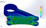
- Front suspension rocker arm FEA mesh
-

- Front suspension rocker arm FEA results
-

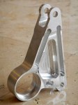
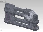
- Front suspension rocker arm CNC machined part
-

- Rear suspension rocker arm FEA mesh
-
- Rear suspension rocker arm FEA results
-
- Rear suspension rocker arm CNC part
-
- Left steering arm FEA mesh
-

- Left steering arm FEA results
-

- Left steering arm CNC part
-

- Stub axle FEA mesh
-

- Stub axle FEA results
-
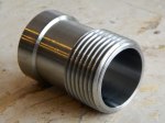
- Stub axle CNC part, chrome-moly steel
Building the Body Buck: Part 2, Putty, Prime, Repeat

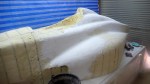
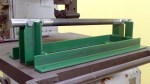
After the first coat of ultra-hard Sikafloor epoxy
Here’s where the heavy lifting begins. Many, many passes of plaster or putty, sanding, and primer. The first step was to coat the entire body in plaster, which is best done the messy way: just plunge your hand into the bucket of plaster and smear it on the body buck. Plaster is much better for filling voids than foam is. Especially the insulation foam that comes in a can. Don’t, under any circumstances, use the canned spray foam. It remains flexible permanently, and keeps slowly expanding over a period of weeks or months. If you use it, as I did, to fill voids, you’ll spend days and days digging it out wherever it reaches the surface, refilling the holes with auto body filler.
I discovered that spackling compound, made for smoothing house walls before painting, works great after the plaster. Plaster has a short working time, and you end up mixing lots of little batches when you’re filling ripples. The spackling compound goes on smoothly, you can work it just about as long as you want, it sands extremely easily, and it sands to a feather edge. I also tried gypsum, but it has the disadvantage of remaining water soluble as it doesn’t cure.
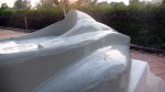
I put on a gallon of Jotun Penguard 2-part enamel filler, then found the only auto-body paint supply shop in town and discovered “sprayable body putty”, so I followed up with a couple of gallons of that, spackling and sanding between coats. About the third coat of sprayable body putty, I noticed that the body buck was swelling badly where it had been in the sun. Uh-oh. It turns out the foam expands and contracts with temperature. After that I kept the car only in the garage, never letting sun touch it. It took 2-3 weeks to fix that mistake, now using auto body filler and a double-action (DA) air-powered sander with 40 grit sandpaper, a great combination for this work.
So when I finally got that mess cleared up, I wasn’t too keen on spraying another coat of primer and potentially distorting the surface again. Instead, I went straight to an extra-hard epoxy used for floors, called Sikafloor. This is a very unusual paint as it’s intended to be used only on horizontal surfaces, where it remains liquid for a long time as it flows to become perfectly flat. I sprayed it on, almost unthinned, an “off label use”, but it worked great for my purposes.


Fabricating the Suspension Attachment Points
-

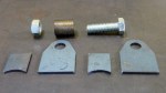
- Aluminum and steel parts back from the laser cutting shop
-
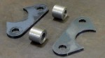
- Upper front before welding
-

- Upper front after welding
-
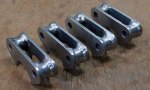
- Set of four completed
-

- Upper rears
-

- Set of eight completed
-
- Rear toe rod attachment point before assembly
-
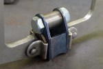
- Rear toe rod attachment point assembled and clamped for welding
-

- Rear toe rod attachment point after welding
Hot Off the (3D) Press: Suspension Upright 3-D Print
The suspension uprights have gone through a long evolution, but I’m zeroing in on the goal.
First Design: Machined Billet Aluminum
This design uses radial-style brake caliper mounting. Needed to be redesigned when someone ordered the lug-mount calipers and had them delivered all the way from the USA. Probably a Freudian slip as they’re less expensive.

Second Design: Fabricated Steel

Second design was fabricated from steel. Unfortunately, welding will eliminate the temper in the heat-affected zones. The weakening due to this is hard to predict, and can only be eliminated by heat treatment. That would mean days or weeks finding and learning to deal with a heat-treatment supplier.

Mesh used for finite-element analysis of fabricated steel upright.

Finite-element analysis stress plot for fabricated upright. Strong enough, but where are those heat-affected zones?
Third Design: Cast Aluminum
Here’s the final result of literally hundreds of design revisions, ensuring that the upright is strong enough and as light as possible. This design is made possible by the new technology of 3d printing, which will be used to make the master “plug”, from which molds will be made to cast the actual part. Note that the steering arm is not an integral part of the upright, but is modeled together with the upright because the FEA runs much faster this way.

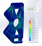
FEA mesh plot for cast upright

FEA stress plot inner

View from outside
Finally, the Master Copy
The upright had to be split into four pieces for 3D printing; split vertically so I can make two mold halves and remove the masters from the molds, and split horizontally to fit the 3D printer. The 3D printer extrudes hot ABS plastic in X-Y layers onto a heated Z-axis stage with 0.3mm resolution. The print is slightly rough and the parting plane is slightly warped, which will have to be corrected with auto body putty, primer, sanding, and paint. The cast aluminum blank will still require several machining steps to cut off the gate and sprue, drill mounting holes, bore the bearing hole and retaining ring slot, and mill the brake caliper mounts. Still far better than trying to machine individual parts (or even a mold pattern) this complex, which would be approximately impossible and semi-infinitely expensive.

One half printed in two colors to highlight the split required to fit it into the 3d printer

Full set of four 3d prints. The cylinder protruding in the upper left is the gate, where molten aluminum will be poured into the finished mold.

Some people get excited by shoe sales. I get excited by this!
Making Chips… Finally!

Lower suspension attachment clevis assembly drawing
It seems that other people who’ve built cars from scratch attempt to get their cars rolling on the ground as soon as possible, so I figure I’ll do it that way too. With that in mind, it’s time to start fabricating the suspension. First up: lower suspension attachment clevises. I ordered 7075 aircraft aluminum from the United States as part of my big shipment. It’s amazing stuff– stronger than steel but light as aluminum. These assemblies have to be extremely strong, as I calculate that under braking the front one takes a load of over 4400 pounds.
-

- Start with a solid chunk of 7075 aircraft aluminum, here scribed for cutting slightly oversize
-

- Blanks are cut to size with thinnest abrasive cutting blade in high-speed angle grinder. I tried using a 12″ cutoff saw, but it couldn’t cut this high-strength aluminum.
-

- Finished raw blank
-

- Facing both sides of the blank with carbide-insert face cutter end mill
-

- Milling holes for bolts to attach to chassis. PDF drawing printed on sticky paper at 1:1 eases the layout and provides a useful double-check against errors.
-

- Milling the first outside radius on the rotary table.
-

- Milling the second outside radius
-

- 45-degree faces are rough cut with the angle grinder, then clevises are supported on V-blocks clamped to the milling machine.
-

- 45-degree faces milled smooth with face cutter
-

- Repeat eight times. Ready for slot milling.
-

- Milling the slots for the rod ends using a ball-end mill.
-

- Milling holes for the rod-end retaining bolts
-

- Milling an additional relief for the rod ends. Test assembly showed interference, so I went back to the computer model and, sure enough, there it was. Now I know to use the interference and clearance detection tools.
-

- Finished lower A-arm clevises. Outside radius on front was also cut on the rotary table / milling machine.
-

- Lower suspension attachment clevis assembly drawing
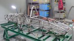
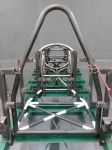
Building the Frame: Roll Hoop to Tail
-

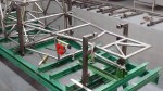
- Removed the chassis from the jigs for the first time. Welded the bottoms of all the joints, which brought the chassis back to true & flat
-

- It’s a commuter car! You can carry it like a briefcase.
-

- Test fitting the rear beltline tubes. Chassis table has pins to locate these tubes, too.
-

- Rear subframe beltline welded…
-
- And into place.
-

- First parts back from the machinists’. Rear keel jig and the keel itself. Beautiful and accurate! Thanks, Somkuan!
-

- Rear keel, ready for welding.
-

- …and welded.
-

- Welded rear keel jig. Really starting to get the hang of this welding stuff. Yay!
-

- Bottom perimeter of the engine compartment fabbed and welded.
-
- Finished rear keel and rear keel jig.
-
- Engine compartment left side lower tubes
-

- Engine compartment right lower diagonal
-

- Bulkhead H right vertical lower tube
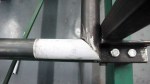
-

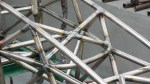
- Another example of how my Solidworks fishmouthed tubes fit, this one at the front end of the rear keel.
-

- Lower diagonal tubes holding the front of the rear keel.
-
- H-J inner upper diagonal tubes securing the front of the rear keel.
-

- H-J bottom perimeter tubes in place. These 3 tubes were welded flat on the table then lifted into place. Here you see the bottom of the car start to curve upward to clear the diffuser.
-

- H-J side diagonals. Here we work our way from front to back to avoid cutting off the ends of the tubes to fit them in from the side.
-
- J left and right lower verticals
-

- J to L left and right lower diagonals
-

- Released from the chassis table again to weld the bottom of all the joints. It’s so much easier this way I don’t even try to weld upside-down anymore.
-
- J-K inner bottom diagonals hold the rear of the rear keel
-

- K-L diagonals secure the rear of the rear keel to the beltline. This is the back end of the frame.
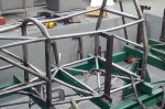
-

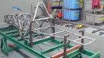
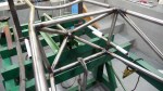
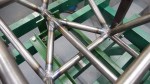
- Top frame rails from the main roll hoop to the back of the car are finally in place. Now we can see the complete outline of the frame.
-
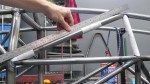
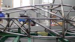
- G-H upper diagonals are curved outwards to allow us to remove the engine from the top. The curve must be in the correct plane.
-
- From this angle you can see the curve. Removing the engine from the top is a design change based on feedback from the ApexSpeed.com forum. Top rail will be made removable later.
-

- H bulkhead, upper left vertical. Note that it’s not really vertical, but leans forward and inward.
-

- Test fitting the G-J upper diagonals. Sometimes it’s necessary to fit a bunch of tubes before welding any in place.
-
- Now we start welding them in place from front to rear. These are the G-H upper diagonals.
-

- H, H-J, J upper tubes (6). Skipped a couple of photos…
-
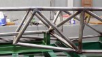
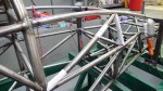
- It’s almost done. Just a few inner diagonals left.
-

- J bulkhead, inner diagonal UL-LR. This area of the frame is extremely strong as it has to support the suspension rockers and engine mounts.
-
- J bulkhead inner diagonals, LL-UR, 2 pieces
-

- H-J inner diagonals support the rear engine mounts.
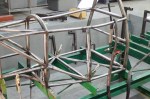
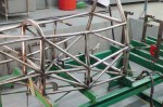
Building the Cockpit
Time for a photo update showing how I built the cockpit, tube by tube.
-
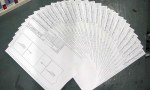
- A complete set of tube drawings for one forumula 1000 cockpit. It’s a lot of work to generate these drawings, but it saves a lot of time in fabrication, and ensures the frame is accurate
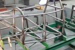
-
- Test fitting the tubes for the cockpit floor
-
- Now we can see the main roll hoop was fabricated too narrow. The holes on the jigs don’t line up properly with the roll hoop
-
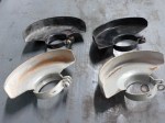
- Found the hidden stash of angle grinder shields removed by my Thai workers. In Thailand, workers just laugh at safety measures. I’ve even had one quit when I insisted he wear eye protection.
-

- Main roll hoop cut and bent to proper size. Sigh…
-

- Test fitting the revised roll hoop
-
- A new bottom member was fabricated for the main roll hoop
-

- Tack welding the revised main roll hoop
-

- Once again test fitting the main roll hoop
-

- Main roll hoop fully welded. Looks much better.
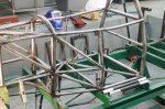
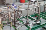
-
- Four outside cockpit frame rails in place
-

- Left side vertical tube in place
-
- Left front lower diagonal in place
-
- Left front middle horizontal and upper diagonal tubes in place
-
- Right side vertical in place
-
- Right front lower diagonal and middle horizontal tubes in place
-

- Left rear lower diagonal tube in place
-

- Right rear lower diagonal tube in place
-
- Two rear middle horizontal tubes in place
-

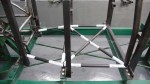
- Main roll hoop brace extensions in place. These are required by SCCA rules to be a minimum of 1″ diameter and 2 mm thickness.
-

- Two upper rear diagonal tubes in place
-

- Daughter Senna (yes, that’s her real name) tries out the driving position, reports that it “needs work.”
